5 Installation at Site
28 of 68
Calio
1157.821/04-EN
5.6.1.6 Connecting the Modbus system
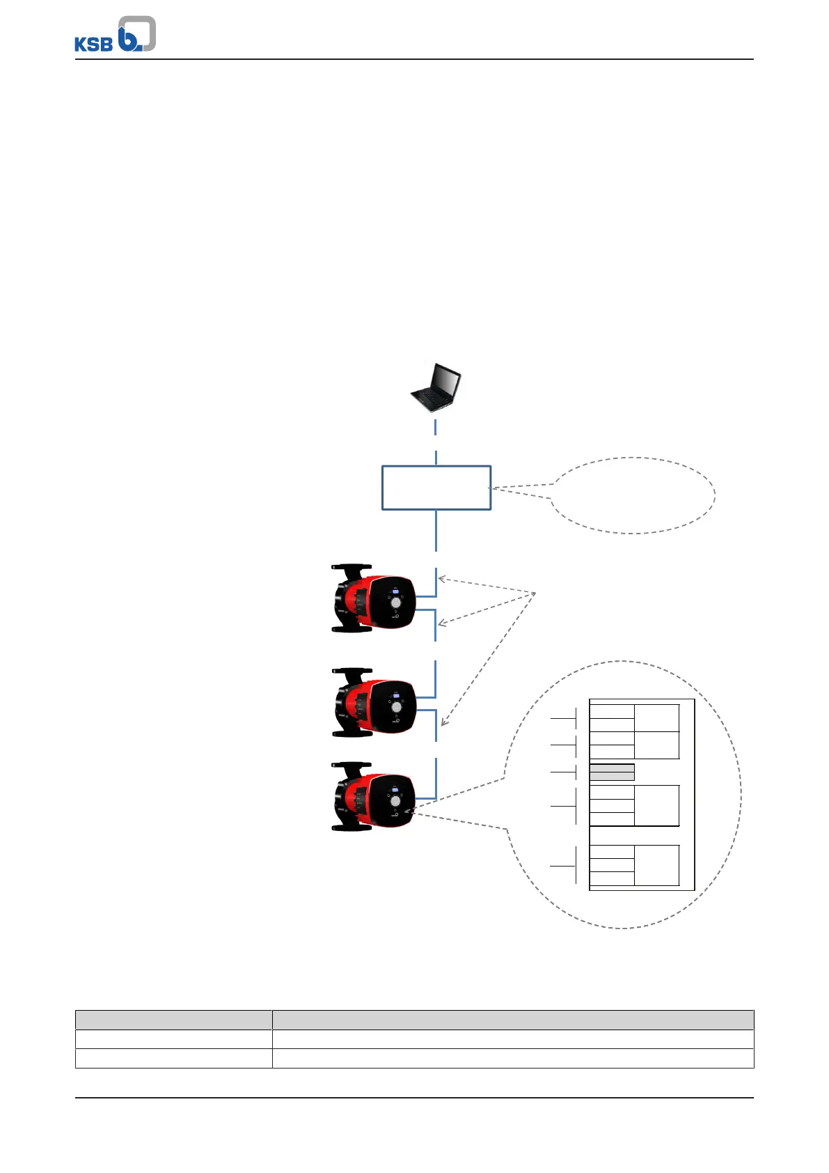
Connection to higher-level automation systems per Modbus at the example of four
pumps
Communication between the connected pump sets and the Modbus master is
effected via Modbus. Cable reflections occur at the open cable ends (first and last
connection of a bus system). The higher the selected baud rate, the larger the cable
reflections. Provide terminating resistors to establish a defined rest potential and
keep reflections to a minimum.
ü The control unit has been de-energised.
1. Wire the pumps at their Modbus terminals in line topology as illustrated.
ð Use a network cable with a defined wave impedance (cable typeB to
TIA-485-A).
2. Connect a terminating resistor of 120Ω to the first and last Modbus device of a
bus line.
Adress 1
Adress n
Modbus
Modbus
Modbus
Modbus-Master
Connection to a building management system (BMS)
Wire the bus terminating
resistor to the master /
enable it
Modbus network cable
with defined wave impedance
(e.g. Ethernet cable)
COMRUN
DUAL0-10 V
L
Vin
0 V
R
1
2
D-
D+
H
0 V
0 V
0 V
a1
a2
a3
a4
a5
Adress n-1
Fig.13: Modbus wiring for the pump sets
Connection to bus systems with Modbus
Table8: Technical data of the Modbus interface
Parameter Description/value
Terminal cross-section 1,5mm
2
Interface RS485 (TIA-485-A) optically isolated
 Loading...