5 Installation at Site
27 of 68
Calio
1157.821/04-EN
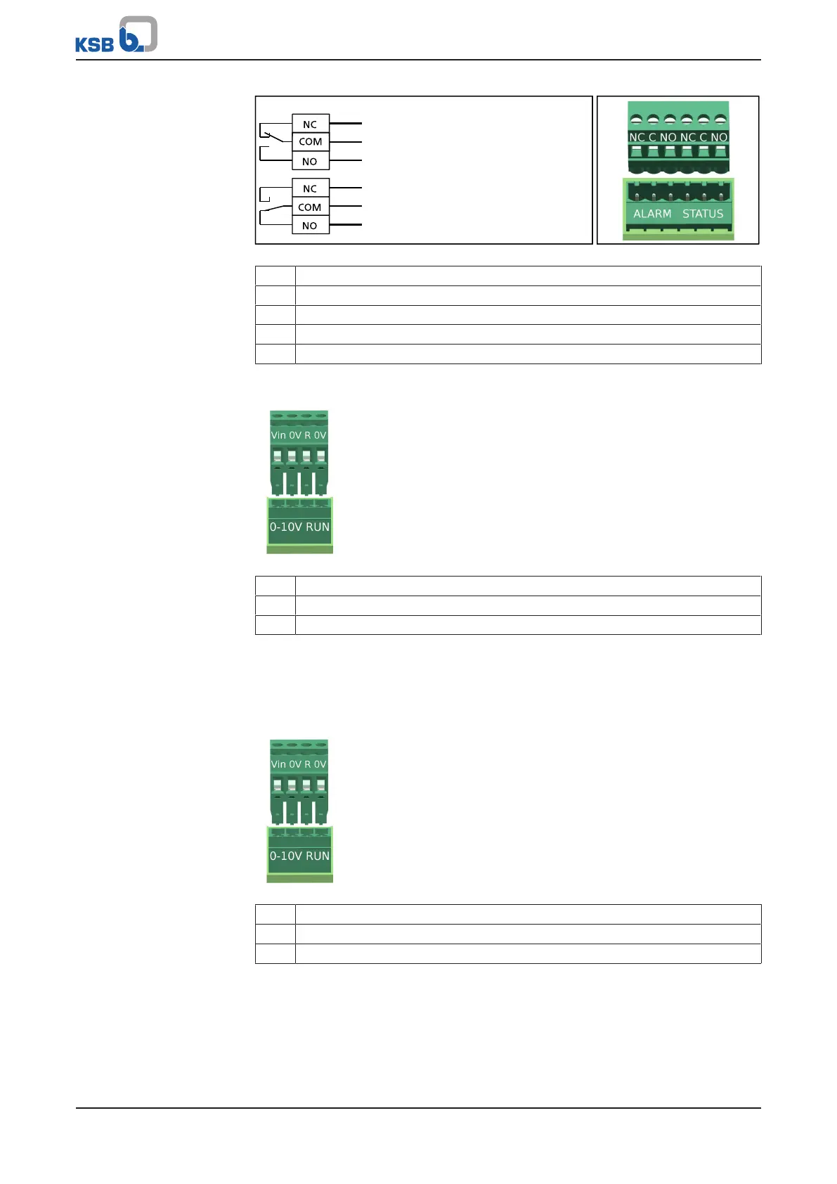
Fig.10: Wiring diagram for the general fault message
1 No general fault message or no power supply/ no alarm active
2 General fault message (rotor not rotating)/ alarm active
NC NC contact, normally closed and electrically conductive connection to C
COM Reference potential for either contact that is closed
NO NO contact, normally open and not electrically conductive connection to C
5.6.1.4 External analog 0-10V DC signal
Fig.11: Terminal pair 0-10V
Vin 0-10V (+)
R Signal 5V (+)
0V GND (-)
ü The wiring diagram is on hand. (ðSection10.2,Page64)
1. Connect the external analog signal to the 0-10V terminal pair integrated in the
pump set.
5.6.1.5 External start/stop
Fig.12: RUN terminal pair
Vin 0-10V (+)
R Signal 5V (+)
0V GND (-)
ü The wiring diagram is on hand. (ðSection10.2,Page64)
1. Unscrew the cable glands (IPX4D).
2. Wire the external signal (volt-free switching contact) to the RUN terminal pair
integrated in the pump set. The terminal pair is supplied bridged.
3. Tighten the cable glands (IPX4D).
 Loading...