5 Installation at Site
31 of 68
Calio
1157.821/04-EN
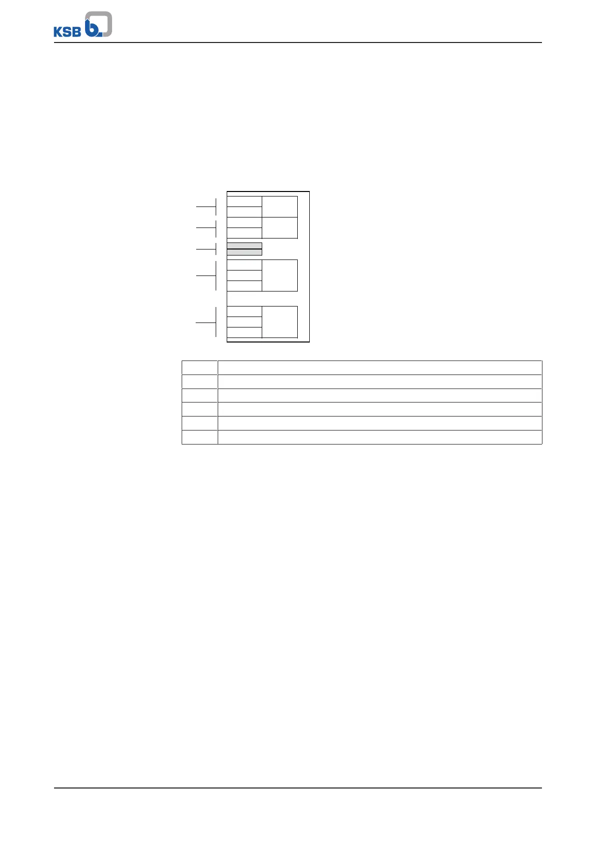
5.6.1.7 Connecting dual-pump configurations
Wire the two pumps to each other with a suitable network cable (wave impedance
120Ω), via the terminal pairs DUAL (a5).
Setting
Make sure the settings and wiring of both pumps are identical to ensure that the
changeover from duty pump to stand-by pump will not have any impact on the duty
point and operating mode. Connect the control modules of the two pumps with a
commercial, shielded data cable. The terminals of the RUN terminal pair must be
bridged at both pumps.
COMRUN
DUAL0-10 V
L
Vin
0 V
R
1
2
D-
D+
H
0 V
0 V
0 V
a1
a2
a3
a4
a5
Fig.16: Terminal wiring diagram for dual-pump configuration
a Data line connections
a1 External 0-10V
a2 External start/stop
a3 Terminating resistor for Modbus cable (DIP switches)
a4 Modbus
a5 Dual-pump configuration
 Loading...