5 Installation at Site
30 of 68
Calio
1157.821/04-EN
Example:
Terminating resistor = 120Ω
Wave impedance of network cable = 120Ω
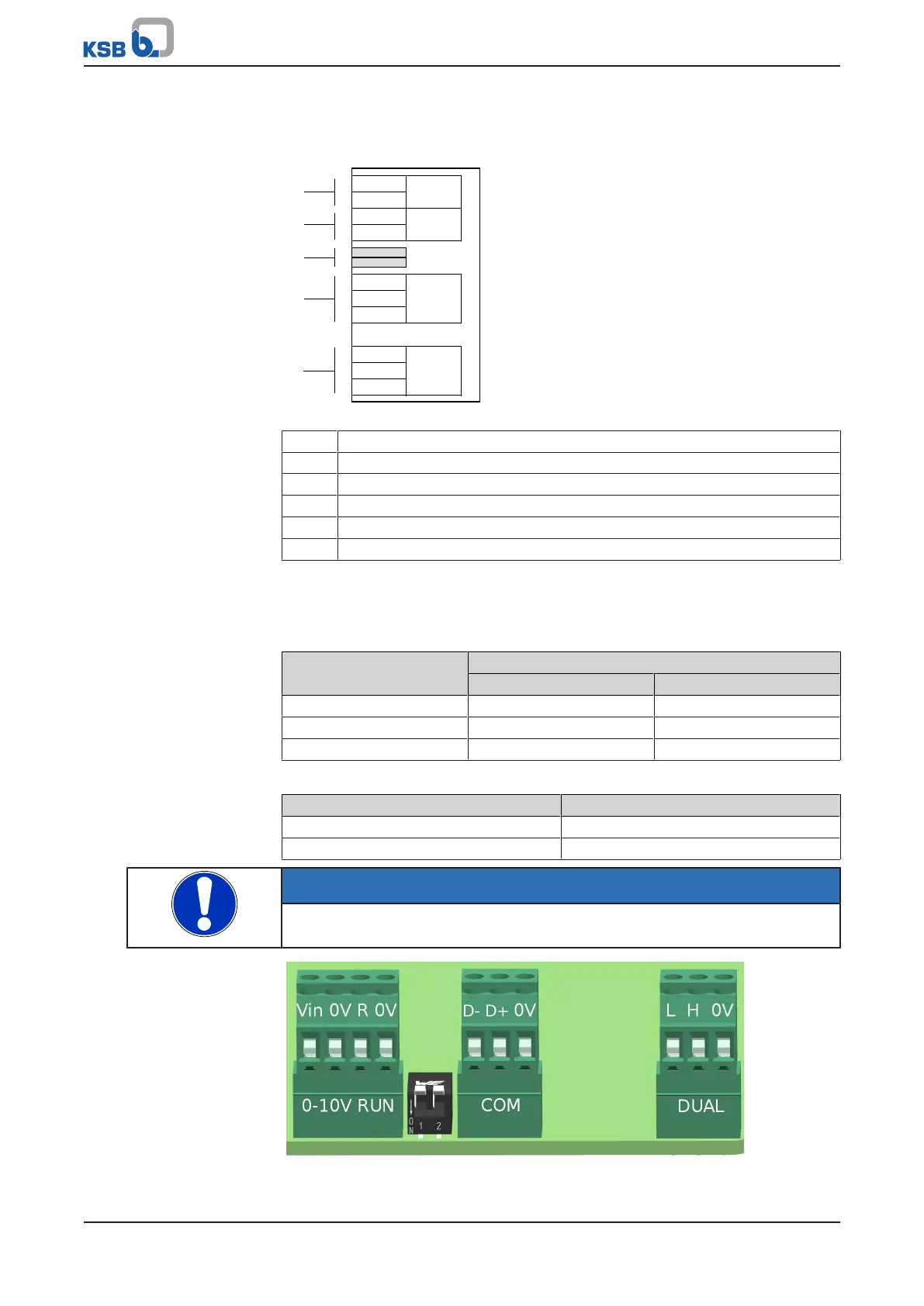
COMRUN
DUAL0-10 V
L
Vin
0 V
R
1
2
D-
D+
H
0 V
0 V
0 V
a1
a2
a3
a4
a5
Fig.14: Terminal wiring diagram for the Modbus data line
a Data line connections
a1 External 0-10V
a2 External start/stop
a3 Terminating resistor for Modbus cable (DIP switches)
a4 Modbus or KSB ServiceTool
a5 Dual-pump configuration
The terminating resistor is enabled when the corresponding pump-integrated DIP
switch in the terminal wiring compartment next to the Modbus terminal pair is
enabled. See illustration.
Table9: Key to the terminal codes
Terminal code Description
RS485 Modbus
D- A- D0
D+ B+ D1
0V COM COM
Table10: Settings of Modbus terminating resistors
Position of DIP switches 1 and 2 Status
ON Modbus terminating resistor enabled
OFF Modbus terminating resistor disabled
NOTE
The two DIP switches 1 and 2 must both be set to the same status.
Fig.15: Illustration of terminals
 Loading...