✓ The foundation has been prepared in accordance with the dimensions given in
the outline drawing/general arrangement drawing.
1.
Position the pump set on the foundation and align it with the help of a spirit
level placed on the shaft and discharge nozzle.
Permissible deviation: 0.2 mm/m.
2. Use shims (2) for height compensation, if necessary.
Always fit shims between the baseplate/foundation frame and the foundation
itself; always insert them to the left and right of the foundation bolts (4) and in
close proximity to these bolts.
For a bolt-to-bolt clearance > 800 mm, fit additional shims (3) halfway between
the adjoining holes.
All shims must lie perfectly flush.
3. Insert the foundation bolts (4) into the holes provided.
4. Use concrete to set the foundation bolts (4) into the foundation.
5. Wait until the concrete has set firmly, then align the baseplate.
6. Tighten the foundation bolts (4) evenly and firmly.
7. Grout the baseplate using low-shrinkage concrete with a standard particle size
and a water/cement ratio of ≤ 0.5.
Produce flowability with the help of a solvent.
Perform secondary treatment of the concrete to DIN 1045.
NOTE
For low-noise operation contact KSB to check whether the pump set can be installed on
anti-vibration mounts.
NOTE
Expansion joints can be fitted between pump and suction/discharge line.
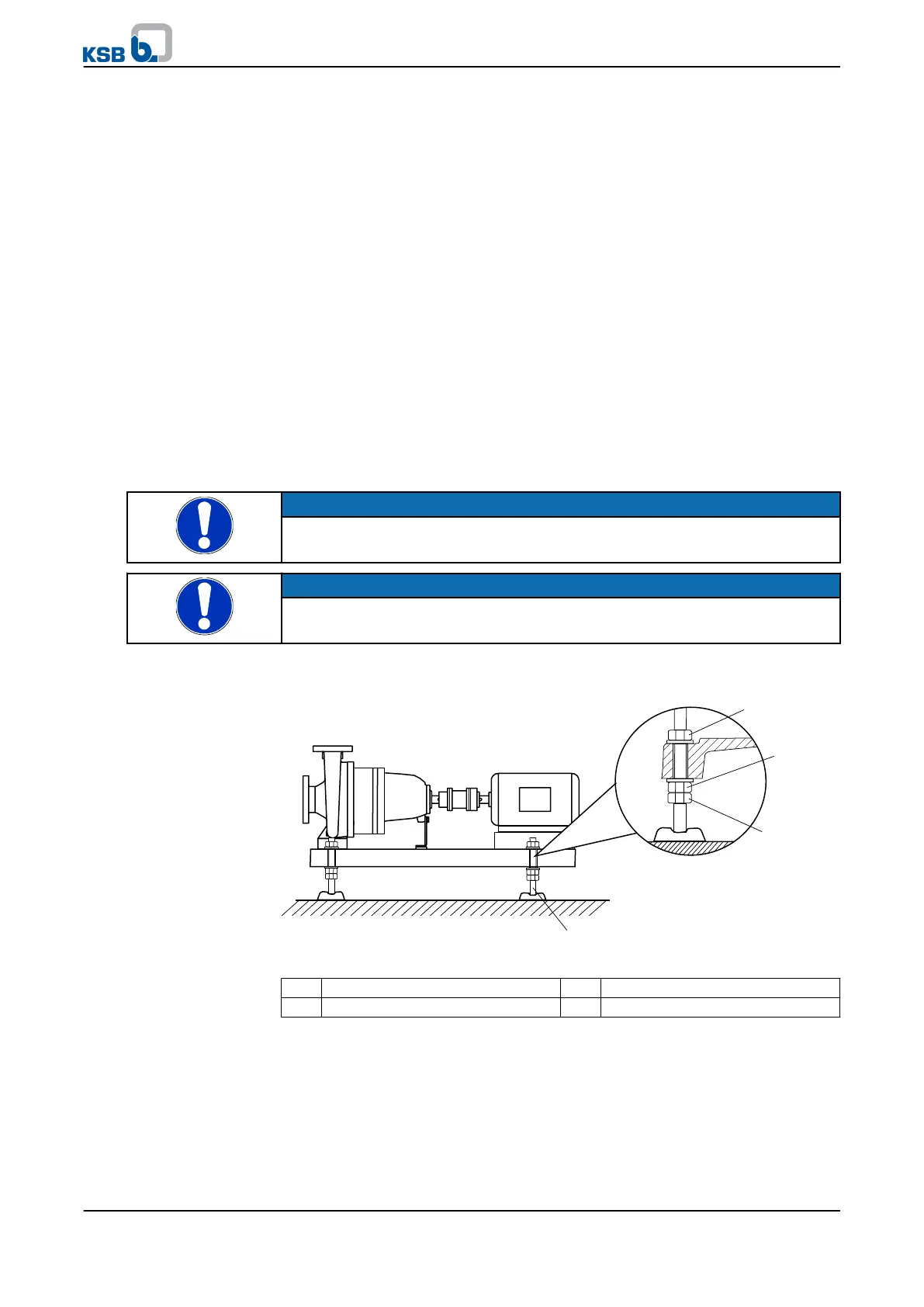
5.3.2 Installation without foundation
Fig. 10: Adjusting elements
1, 3 Lock nut 2 Adjusting nut
4 Adjusting element
✓ The installation surface has the required strength and characteristics.
1.
Position the pump set on the adjusting elements (4) and align it with the help of
a spirit level (on the shaft/discharge nozzle).
2. To adjust any differences in height, loosen the bolts and lock nuts (1, 3) of the
adjusting elements (4).
3. Turn the adjusting nut (2) until any differences in height have been
compensated.
5 Installation at Site
KWP
23 of 78