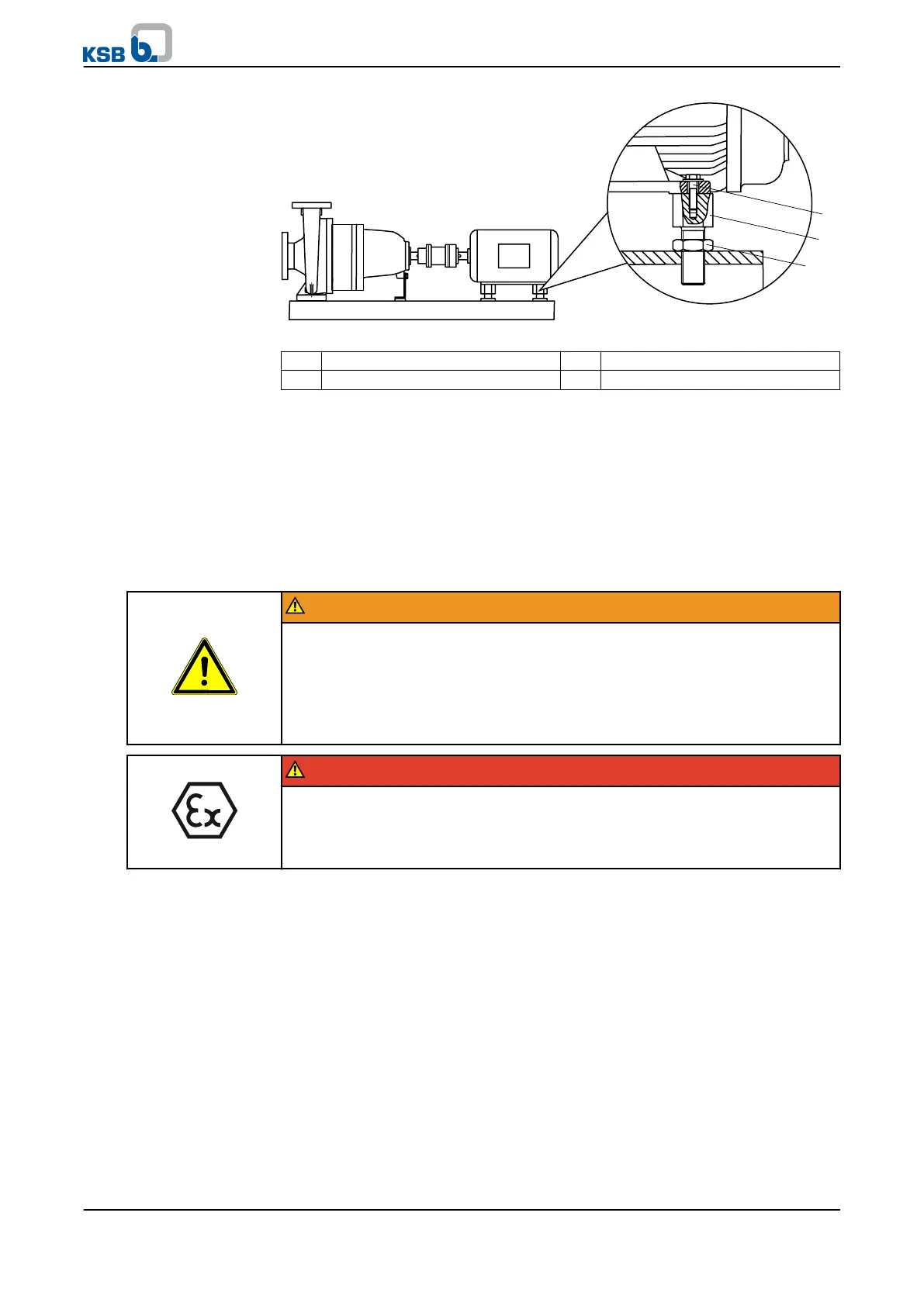
Fig. 16: Motor with levelling screw
1 Hexagon head bolt 2 Levelling screw
3 Lock nut
✓ Misalignment of the coupling (⇨ Section 5.6.1 Page 30).
✓ Coupling guard and step guard, if any, have been removed.
1.
Loosen the hexagon head bolts (1) at the motor and the lock nuts (3) at the
baseplate.
2. Turn the levelling screws (2) by hand or by means of an open-jawed wrench until
the coupling alignment is correct.
3. Re-tighten the hexagon head bolts (1) at the motor and the lock nuts (3) at the
baseplate.
4. Check that the coupling and shaft can easily be rotated by hand.
WARNING
Unprotected rotating coupling
Risk of injury by rotating shafts!
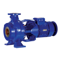
▷ Always operate the pump set with a coupling guard.
If the customer specifically requests not to include a coupling guard in KSB's
delivery, then the operator must supply one!
▷ Observe all relevant regulations for selecting a coupling guard.
DANGER
Risk of ignition by frictional sparks
Explosion hazard
!
▷ Choose a coupling guard material that is non-sparking in the event of
mechanical contact (see DIN EN 13463-1).
5. Reinstall the coupling guard and step guard, if any.
6.
Check the distance between coupling and coupling guard.
The coupling guard must not touch the coupling.
5.7.2 Motors without levelling screw
Any differences in shaft centre height between the pump and the motor are
compensated by means of shims.
5 Installation at Site
KWP
33 of 78