RDL
18
Please check if a strainer/filter should be fitted in the suction line during the commissioning stage, in
order to protect both the pump and the shaft seal from damage due to contamination from the plant.
In order to avoid any marked deterioration of the NPSH available, which would have an adverse effect on the pump, the
strainer has to be cleaned whenever required. It is recommended to use a differential pressure gauge to detect any strainer
clogging (see 6.1.6).
For installation on a foundation with vibration insulation please take into account the when
connecting the piping that the flexible elements at the baseplate may only compensate compressive and
shearing strains within the admissible limits. Tensile strains cannot be compensated for, therefore the flexible
elements shall only be firmly fastened to the foundation after connecting the piping.
5.6.1 Recommendation for suction piping
Assembly of suction piping should comply with the following consideration:
a) only after completing the grout set, piping can be connected to the pump flange;
b) suction piping, as much as possible, should be short and straight, avoiding losses, and totally drained preventing air from
entering;
c) to be free of air pockets, in case of horizontal and negative suction, the piping should be installed with a slope in direction
to the suction;
d) nominal diameter of pump suction flange does not determine the nominal diameter of suction piping. For calculation of
ideal diameter, as referential, use the flow speed established between 1 and 2,5 m/s (3 and 8 ft/s);
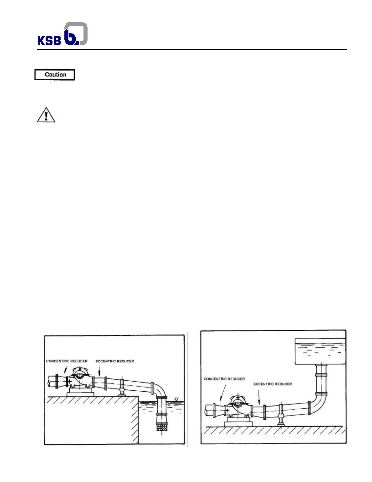
e) when reducer is necessary, this should be eccentric and with the flat side located on the top as fig. 18. in order to avoid
formation of air pockets;
f) elbows, when necessary, should be designed and installed providing lower losses. Ex.: prefer elbow of long or medium
radius;
g) piping flange should adjust to the pump suction nozzle, totally free of tensions, without transmitting any stress to the pump
casing. Pump should never be support for the piping. If it is not observed misalignment can occur and its consequences
like parts scratch and other serious damages;
h) in installation where foot valve is applicable observe that the passage area should be 1.5 time bigger than the piping area.
Usually coupled to the foot valve should exist a strainer with a free passage of 3 to 4 times bigger than the piping area;
i) when the pumped liquid is subject to high temperature variation expansion joints should be installed to avoid piping
stresses caused by dilation and contraction of the pump;
j) in positive suction it is recommended to install a valve in order to close the flow as necessary. During pump operation it
must be totally opened. Suction with only one suction header for several pumps must have one valve for each pump and
the connection between the suction header and the suction piping should always be with changes of direction lower than
45º. In all these cases with use of gate valve, the shaft of it should be disposed horizontally or vertically down;
k) In order to avoid turbulence, air entering, sand or mud in the pump suction use HI the recommendations;
l) Check coupling alignment after tightening piping;
m) To facilitate piping assembly and parts adjustment, install, when necessary, Dresser type assembly joint, common or
special type with tie bolts.
Fig. 17 – Negative suction Fig. 18 – Positive suction