RDL
17
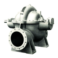
This alignment should be performed with the help of a dial indicator for the control of the radial and axial displacements. Fix the
bottom of the instrument to the periphery of one of the coupling halves, adjust the position of the dial indicator perpendicular to
the periphery of the another half of the coupling. Move the dial to zero and move by hand the coupling half in which the
instrument bottom is fixed, making the dial indicator to complete a 360
o
. turn. See Fig. 16.
The same procedure should be performed to control the axial displacement. See Fig. 17.
Fig.16 – Radial control Fig.17 – Axial Control
To correct the alignment, loosen the driver bolts, sliding it laterally or inserting shims to correct its height as necessary.
Axial and radial alignments should be within the tolerance of 0,1 mm (0.004”) with the driver and pump fixing bolts tightened.
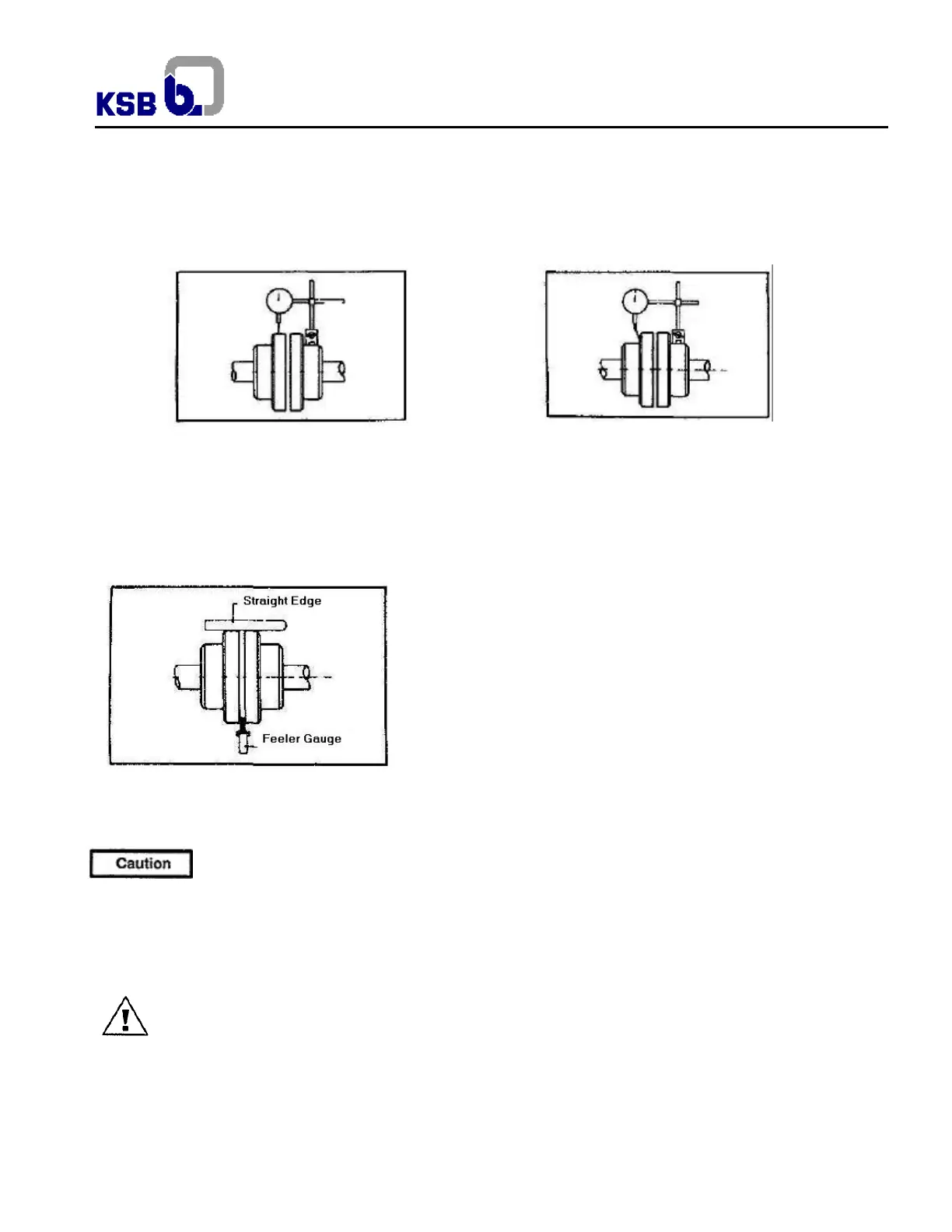
If there is no dial indicator available, use a straight edge across the two parts of coupling sleeve. The control should be done on
the horizontal and vertical planes. To control axially use a feeler gauge. See Fig. 18. Observe the coupling sleeve hub
clearance specified by the manufacturer.
Fig.18 – Alignment with straight edge and feeler gauge
5.6 Connecting the piping
Never use the pump itself as an anchorage point for the piping. The permissible pipeline forces must not be
ceeded (see exceeded (see table 1).
Suction lift lines shall be laid with a rising slope towards the pump and suction head lines with a downward slope towards the
pump. The pipelines shall be anchored in dose proximity to the pump and connected without transmitting any stresses or
strains. The nominal diameters of the pipelines shall be at least equal to the nominal diameters of the pump nozzles. Connec-
tion flanges must be parallel to the pump flanges it is recommended to install check and shut-off elements in the system,
depending on the type of plant and pump. It must be ensured, however, that the pump can still be drained and dismantled
without problems. Thermal expansions of the pipelines must be compensated by appropriate measures so as not to impose
any extra loads on the pump exceeding the permissible pipeline forces and moments.
An excessive, impermissible increase in the pipeline forces may cause leaks on the pump where the medium
handled can escape into the atmosphere.
This may lead to danger to human life when toxic or hot media are handled!
The flange covers on the pump suction and discharge nozzles must be removed prior to installation in the piping.