RDL
16
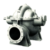
Fig.13 – Grouting
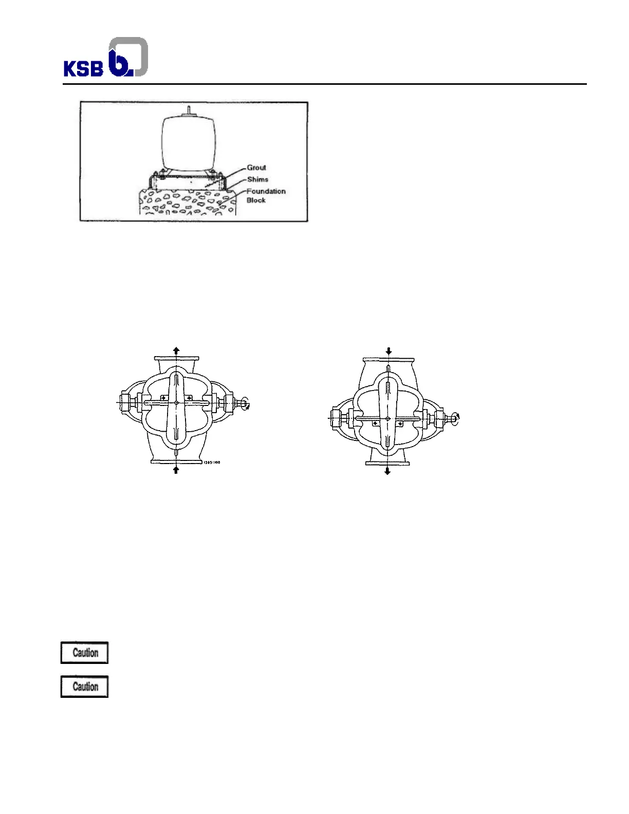
5.4 Rotation direction
KSB RDL Pumps can be coupled to the drive on both shaft ends. The rotation can be clockwise or counter-clockwise, a
function of drive position and suction and discharge nozzles. To determine the rotation direction, be in front of the shaft drive
side and look at the pump, follow the pumped liquid flow, which enters through the suction flange (bigger diameter), makes a
complete turn inside the pump and goes out through the discharge flange (smaller diameter). See figures 14 and 15.
If the shaft is assembled in one determined position, it can be reversed without special adaptation.
Fig.14 – Counter Clockwise rotation Fig.15 – Clockwise rotation
5.5 Coupling Alignment
The useful life of the rotor assembly and its operation free of irregular vibrations will rely on the perfect alignment between the
pump and the driver.
The alignment performed at the factory must be re checked due to the fact that during transportation and handling, the motor-
pump assembly is exposed to deformations, which may affect the initial alignment.
The following instructions also apply to units not mounted on a common baseplate.
After connecting the piping and priming the
system, it is essential to re-check the alignment at operating temperature.
Incorrect alignment and inadmissible coupling displacement will affect the operating behavior and may result in
damage to the bearings and shaft seals as well as premature coupling wear.
After the grouting has set hard, perform the alignment, if possible, with the suction and discharge pipe lines already connected.