RDL
7.6.1 Disassembly sequence for pumps with packing
Close suction (if any) and discharge valves. Drain pump removing threaded plugs (903.3) and (903.1).
Close valves and disconnect auxiliary pipings, manometers and vacuometers (if any). Remove coupling guard (if any).
Disconnect coupling sleeve of driver. Loosen nuts (920.4) and gland cover (452) of its studs (902.4), displacing into bearing
direction.
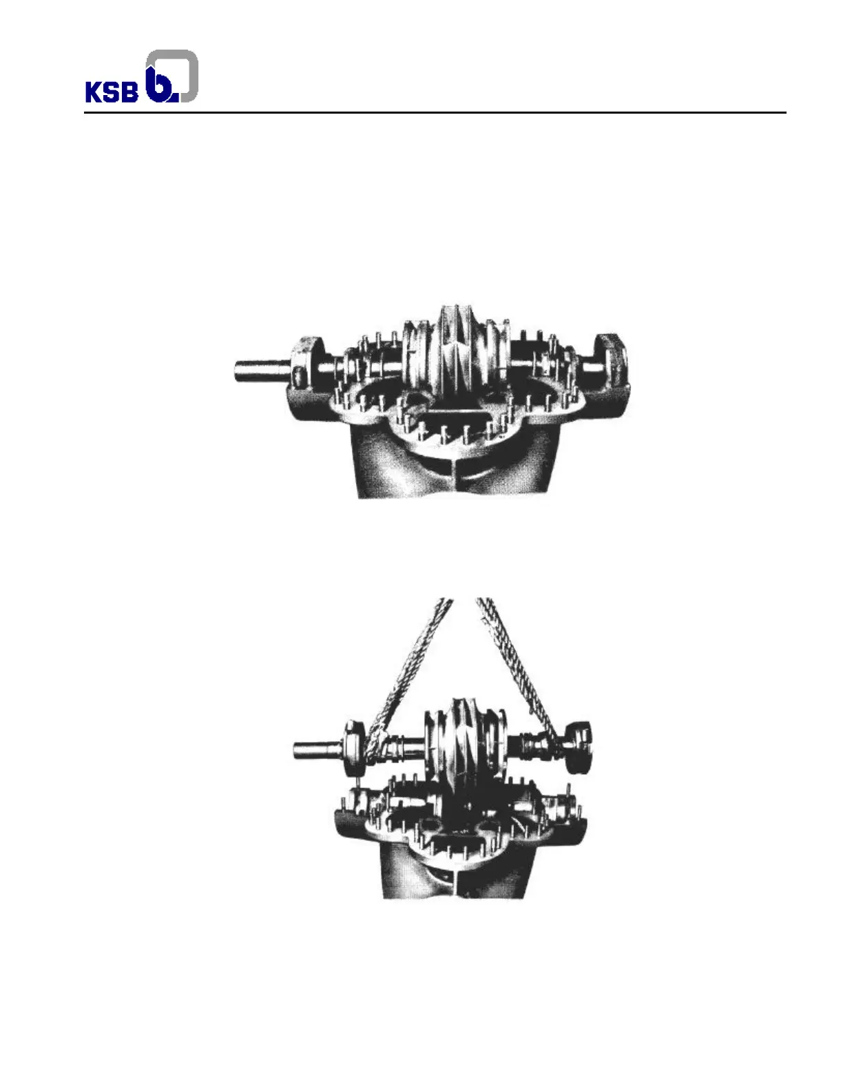
Loosen nuts (920.2), (920.3) and (920.5), (if any). Tighten nuts (920.6) to extract both guide pins (560.1). Separate upper
casing (105.2) from lower casing (105.1) tightening extractor bolts uniformly (901.1). Pull extractor bolts back to not hinder
during assembly. Pass the string around each eyebolt of upper casing and lift it. Thereafter pump inside is available for
inspection. See fig. 26
Fig.26 – Pump with upper casing removed, available for inspection
Fig.27 – Lift and extracting of rotor from inside the lower casing