RDL
Pass a rope around the shaft between the gland covers and bearing housings and lift the rotor to extract it from lower casing.
See fig. 27. Take care to not damage the studs (902.1) and that the extracting is done without effort due to friction or bent
position of rotor. Extract coupling sleeve with a pull out device and the key (940.3). Loosen nuts (901.2) and bearing cover of
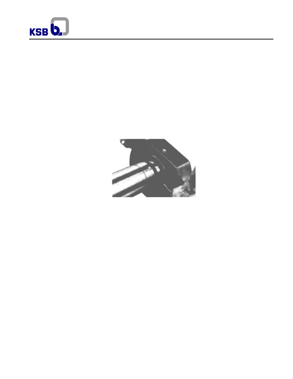
drive side (360.1). For pumps with DN 400 mm or above, there are two extract holes M8 (5/16”) in the rear part of bearing
housings. By means of uniform tighten of two bolts relatively long in these tapped holes, remove external ring of bearing. See
fig. 28. With a pull out device extract bearing housing for pumps DN 400 mm (16”) or bigger, extract also internal ring of bearing
and spacer ring (504). For pumps up to 300 mm extract bearing housing and also ball bearings.
Loosen bolts (901.2) and bearing cover N.D. side (360.2). Unlock lockwasher (931) from bearing nut (923). Loosen bearing nut
with key type nail or with pin. Extract with pull out device shaft from bearing housing, bearing (321) and spacer ring (504).
Thereafter parts are symmetrical in both sides of rotating element and disassembly is similar.
Extract wear rings (502); sealing rings for shaft (420); gland cover (452); gasket rings (461); lantern ring (458) and neck ring
(457).
Loosen screwed pins (940.1) and thereafter shaft nuts (921). Extract shaft protective sleeves (524), taking care not to damage
the O-rings (412). Remove the keys (940.1); spacer sleeves (525.2) if any; spacer sleeves (525.1), except for pumps 200-500,
200-620 and 250-340 which do not have them. Take out the impeller (234) from the shaft and the key (940.2).
Pumps DN 600mm (24”) up to DN 800mm (32”) have bearing brackets (330) fixed in the lower casing which can be
disassembled loosening the nuts (920.8) and guide pins.
Fig.28 – Extracting of external ring of bearing with screw
Note:
a) When extracting bearing housings, avoid uneven effort or blows, that can damage the bearings.
b) If applicable, extract the impeller wear rings (503) loosening threaded pins (904.2).
7.6.2 Disassembly sequence for pumps with mechanical seal
Loosen auxiliary piping (if any) and gland. Apply specific instructions of mechanical seal manufacturer.
7.7 Assembly sequence
All parts must be cleaned and deburred before assembly.
7.7.1 Pump with gasket
Place the key (940.2) on the shaft (211); assemble the impeller (234), spacer sleeves (525.1), except for pumps 200-500, 200-
620 and 250-340; assemble spacer sleeves (525.2), if any. Place the keys (940.1) and assemble shaft protective sleeves (524)
with respective o’rings. Take care to not damage o’rings during assembly. Mount and tighten the two shaft nuts (921) against
the protective sleeves.
Shaft nuts must be only definitely positioned and locked after centering the impeller.
Place the casing wear rings (502) on the external diameter of impeller entrance hub. Mount on the shaft neck rings (457);
lantern ring (458) and gland cover placing them so as not hinder the assembly.
Mount sealing rings for shaft (420).
For pumps sizes 125 up to 300 place radial ball bearing inside the bearing housings pressing them by the external ring. In the
bearing housing, mount the spacer ring (504) at the bottom, before bearing assembly. Heat two sets in the furnace in a
temperature of 120ºC (250ºF) for 30 minutes.
Place them heated on the shaft with the housing (321). Spacer ring (504) must touch in the shaft step. Mount lockwasher (931)
and bearing nut (923). Tighten bearing nut and lock it with one little tongue of lockwasher. Mount also at high temperature
bearing housing drive side with respective bearing (321). The exact position will be defined during the placement of the rotor on
 Loading...