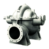
RDL
5
N.B.:
N.B.:
2.9 Explosion protection
If the pumps/units are installed in hazardous areas, the measures and instructions given in the following sections 2.9.1
t be ad to 2.9.6 must be adhered without fail, to ensure explosion protection.
2.9.1 Unit fill
It is assumed that the system of suction and discharge lines and thus the wetted pump internal are completely
filled filled with the product to be handled at all times during pump operation, so that an explosive atmosphere is prevented.
If the operator cannot warrant this condition, appropriate monitoring devices must be used.
In addition, it is imperative to make sure that the seal chambers, auxiliary systems of the shaft seal and the
heating and cooling systems are properly filled.
2.9.2 Marking
The marking on the pump only refers to the pump part, i.e. the coupling and motor must be regarded separately. The
coupling must have an EC manufacture’s declaration. The driver must be regarded separately.
Example of marking on the pump part: Ex II 2 G T1 - T5.
The marking indicates the theoretically available temperature range as stipulated by the respective temperature classes. The
temperatures permitted for the individual pump variants are outlined in section 2.9.5.
2.9.3 Checking the direction of rotation (see also 6.1.4)
If the explosion hazard also exists during the installation phase, the direction of rotation must never be checked by
starting starting up the unfilled pump unit, even for a short period, to prevent temperature increases resulting from
contact between rotating and stationary components.
2.9.4 Pump operating mode
Make sure that the pump is always started up with the suction-side shut-off valve fully open and the discharge-side shut-off
valve slightly open. However, the pump can also be starded up against a closed swing check valve. The discharge-side shut-off
valve shall be adjusted to comply with the duty point immediately following the run-up process (see 6.1).
Pump operation with the shut-off valves in the suction and/or discharge pipes closed is not permitted.
In this condition, there is a risk of the pump casing taking on high surface temperatures after a very short time,
due to a rapid temperature rise in the pumped product inside the pump.
Additionally, the resulting rapid pressure build-up inside the pump may cause excessive stresses on the pump
materials or even bursting.
The minimum flows indicated in tables 4.3 and 4.3.1 refer to water and water-like liquids. Longer operating periods with these
liquids and at the flow rates indicated will not cause an additional increase in the temperatures on the pump surface. However,
if the physical properties of the fluids handled are different from water, it is essential to check if an additional heat build-up may
occur and if the minimum flow rate must therefore be increased.
To check, proceed as described in tables 4.3 and 4.3.1.
In addition, the instructions given in section 6 of this operating manual must be observed.
Both gland packings and mechanical seals may exceed the specified temperature limits if run dry. Dry
running may not only result from an inadequately filled seal chamber, but also from excessive gas content in
the fluid handled.
Pump operation outside its specified operating range may also result in dry running.
In hazardous areas, gland packings shall only be used if combined with a suitable temperature monitoring device.
2.9.5 Temperature limits
In normal pump operation, the highest temperatures are to be expected on the surface of the pump casing, at the shaft
shaft seal and in the bearing areas. The surface temperature at the pump casing corresponds to the temperature of the fluid
handled.
If the pump is heated, it must be ensured that the temperature classes stipulated for the plant are observed.
In the bearing bracket area, the unit surfaces must be freely exposed to the atmosphere.
 Loading...