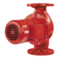
The KSB Trialine / Trialine Z is an in-line pump and in-line twin pump designed for various fluid handling applications. This installation and operating manual provides comprehensive information on its function, technical specifications, usage, and maintenance.
Function Description
The Trialine / Trialine Z pump is designed to transport fluids, converting kinetic energy into pressure energy. It features a back pull-out unit, allowing the complete rotating assembly to be removed from the pump casing without disturbing the piping. This design simplifies maintenance and servicing. The pump set consists of the pump, drive, and additional components and accessories. The motor is directly flanged to the pump via a flange or a drive lantern, and the suction line is connected to the suction nozzle, while the discharge line is connected to the discharge nozzle.
The pump operates by drawing fluid into the suction nozzle (9) and accelerating it outward in a cylindrical path by the rotating impeller (8). The flow profile of the pump casing converts the kinetic energy of the fluid into pressure energy. The fluid is pumped to the discharge nozzle (2), where it leaves the pump. A clearance gap (1) prevents any fluid from flowing back from the casing into the inlet. At the rear side of the impeller, the shaft (7) passes through the motor flange (3). The shaft linkage through the cover is sealed to the atmosphere with a dynamic shaft seal (10). The shaft runs in rolling element bearings (5 and 6), which are supported by a motor housing (4).
Important Technical Specifications
The Trialine / Trialine Z pumps are available in various type series and variants. Key technical specifications include:
- Type Series: Trialine
- Nominal Suction/Discharge Nozzle Diameter: Available in sizes such as 40, 100, and 052 mm.
- Nominal Impeller Diameter: Specified in millimeters.
- Motor Rating: Available in various kW ratings, e.g., 2 x 10 (example 0.55 kW).
- Number of Motor Poles: Specified as 2.
- Qmax: Maximum flow rate, e.g., 22 m³/h.
- Hmax: Maximum head, e.g., 6.6 m.
- Max. Temperature: 120°C.
- PN: Pressure nominal, e.g., PN 10.
- Surface Sound Pressure Level (LpA): For a pump set with a rated power input of 1450 rpm, the max. LpA is 50. For 2900 rpm, the max. LpA is 61. These values are spatial averages as per ISO 3744 and EN 12639, valid for pump operation in the Q/Qopt = 0.80 - 1.1 range and for non-cavitating operation. If noise levels are to be warranted, add 3 dB for measuring and constructional tolerance.
- Design: Close-coupled design/in-line design, single-stage, horizontal/vertical installation, back pull-out design, rigid connection between pump and motor, pump and motor on a common shaft.
- Impeller Type: Closed radial impeller.
- Shaft Seal: Mechanical seal.
- Bearings: Radial ball bearings in the motor housing, grease lubrication.
Usage Features
The Trialine / Trialine Z pumps offer several usage features designed for ease of installation, operation, and safety:
-
Installation at Site:
- Motor Direction: For dry running or ingress of leakage into the motor, ensure the pump set is installed with the "motor below" configuration.
- Rotation Direction: For dual or twin pumps, specified performance data may not be achieved if the direction of rotation is incorrect. Always check the direction of rotation.
- Air in Pump Set: For air in the pump set, the direction of flow from top to bottom is recommended. Fit a vent valve at the highest point upstream of the pump's suction nozzle.
- Piping: Excessive loads acting on the pump nozzles can lead to leakage of hot fluids. Do not use the pump as an anchorage point for the piping. Anchor the pipelines in close proximity to the pump and connect them without transmitting any stresses or strains. Take appropriate measures to compensate thermal expansion of the piping.
- Welding: Incorrect earthing during welding work can damage rolling element bearings. Never earth the electric welding equipment on the pump or baseplate. Prevent current flowing through the rolling element bearings.
- Cleanliness: It is recommended to install check and shut-off elements in the system, depending on the type of plant and pump. Thoroughly clean, flush, and blow through all vessels, pipelines, and connections (especially for new installations).
- Suction Line/Auction Head: The suction lift line/auction head line has been laid with a rising/downward slope towards the pump.
- Nominal Diameter: The nominal diameters of the pipelines are at least equal to the nominal diameters of the pump nozzle.
- Permissible Forces and Moments: No piping-induced forces and moments (from warped pipelines or thermal expansion, for example) must act on the pump set.
- Auxiliary Connections: Malfunction of the pump can occur due to failure to use or incorrect use of auxiliary connections. Use only the auxiliary connections provided.
- Protective Equipment: The volute casing and casing/discharge cover can reach high temperatures. Insulate the volute casing and fit protective equipment.
- Drive Lantern: Heat build-up inside the drive lantern can cause damage to the bearing. Never insulate the casing cover and the drive lantern.
- Connection to Power Supply: Work on the pump set by unqualified personnel can lead to danger of death from electric shock. Always have the electrical connections installed by a trained electrician. Observe regulations IEC 30364 (DIN VDE 0100) and, for explosion-proof pump sets, IEC 60079 (DIN VDE 0165).
- Mains Voltage: Incorrect connection to the mains can cause damage to the mains network or short circuit. Observe the technical specifications of the local energy supply companies. Check the available mains voltage against the data on the name plate. Select an appropriate start-up method.
- Motor Protection: It is recommended to fit a motor protection device.
- Direction of Rotation: The pump's direction of rotation is indicated by an arrow on the pump. Start the pump set and stop it again immediately to determine the motor's direction of rotation. Check the direction of rotation. The motor's direction of rotation must match the arrow indicating the direction of rotation on the pump. If the motor runs in the wrong direction of rotation, check the electrical connection of the motor and the control system, if applicable.
-
Commissioning/Start-up:
- Prerequisites: The pump set must be properly connected to the power supply and equipped with all protection devices. The pump has been primed with the fluid to be handled. The direction of rotation has been checked. All auxiliary connections required are connected and operational. After prolonged shutdown of the pump set, the activities described in Section 6.3 (Page 21) have been carried out.
- Shaft Seal: The mechanical seal only leaks slightly or invisibly (as vapor) during operation. Mechanical seals are maintenance-free.
- Priming and Venting: Increased wear due to dry running can damage the pump set. Never operate the pump set without liquid fill. Never close the shut-off element in the suction line and/or supply line during pump operation. Vent the pump and suction line and prime both with the fluid to be handled. Fully open the shut-off element in the suction line.
- Hot Fluid Escaping: Hot fluid escaping under pressure when the vent plug is opened can cause risk of electric shock and scalding. Protect the electric components against escaping fluid. Wear protective clothing (e.g., gloves).
- Gas Volume: For design-inherent reasons, a remaining gas volume in the hydraulic system cannot be excluded after the pump has been primed for commissioning/start-up. However, once the pump is started up, the pumping effect will immediately fill this volume with the fluid handled.
- Start-up: Non-compliance with permissible pressure and temperature limits can damage the pump. Leakage of hot fluids can occur. Never operate the pump with the shut-off elements in the suction line and/or discharge line closed. Only start up the pump set with the discharge-side gate valve slightly or fully open.
- Dry Running: Excessive temperatures due to dry running can damage the pump set. Never operate the pump set without liquid fill. Prime the pump as specified. Always operate the pump within the permissible operating range.
- Abnormal Noises, Vibrations, Temperatures or Leakage: Can damage the pump. Switch off the pump set immediately. Eliminate the causes before returning the pump set to service.
- Piping: The system piping has been cleaned. Pump, suction line, and inlet tank, if any, have been vented and primed with the fluid to be handled. The filling and venting lines have been closed. Fully open the shut-off element in the suction head/suction lift line. Close or slightly open the shut-off element in the discharge line. Start up the motor.
- Seal Leakage: Seal leakage at operating temperature can cause hot fluid to escape. Once the operating temperature has been reached, re-tighten the hexagon nuts between casing and casing cover. When the operating temperature has been reached and/or in the event of leakage, switch off the pump set and re-tighten the bolts between lantern and casing.
- Shutdown: Heat build-up inside the pump can damage the shaft seal. Depending on the type of installation, the pump set requires sufficient after-run time until the heat source switched off and the fluid handled has cooled down. The shut-off element in the suction line is and remains open. Close the shut-off element in the discharge line.
- Standstill: Switch off the motor and make sure the pump set runs down smoothly to a standstill.
- Check Valve: If the discharge line is equipped with a non-return or check valve, the shut-off element may remain open as long as there is some back pressure.
- Prolonged Shutdown: For prolonged shutdown periods, close the shut-off element in the suction line.
- Freezing: Risk of freezing during prolonged pump shutdown periods can damage the pump. Drain the pump and the cooling/heating chambers (if any) or otherwise protect them against freezing.
- Operating Limits: Non-compliance with operating limits for pressure, temperature, and speed can cause hot fluid to escape. Comply with the operating data indicated in the data sheet. Avoid prolonged operation against a closed shut-off element. Never operate the pump at product temperatures exceeding those specified in the data sheet or on the name plate.
- Ambient Temperature: Operation outside the permissible ambient temperature can damage the pump set. Observe the specified limits for permissible ambient temperatures.
- Density of Fluid Handled: The power input of the pump increases in proportion to the density of the fluid handled.
- Motor Overload: Impermissibly high density of the fluid handled can cause motor overload. Observe the information on fluid density indicated in the data sheet. Make sure the power reserve of the motor is sufficient.
Maintenance Features
Regular maintenance is crucial for the longevity and optimal performance of the Trialine / Trialine Z pump.