Measuring principle d 76.3 Hz Time interval
(Period measurement)
> 76.3 Hz Gate time
Gate time approx. 13.1 ms
Measuring error < 0.1% per channel
Response time of the outputs:
1-channel operation < 100 ms @ 40 kHz
< 350 ms @ 65 kHz
2-channel operation < 150 ms @ 40 kHz
< 600 ms @ 65 kHz
11.4 Timer
Seconds 0.001 sec ... 999 999 sec
Minutes 0.001 min ... 999 999 min
Hours 0.001 hrs . 999 999 hrs
Hrs.Min.Sec 00hrs.00min.01sec ...
99hrs.59min.59sec
Min. time measurable 500µs
Measuring error < 100 ppm
Output response time: < 13 ms
11.5 Signal and Control Inputs
SELV circuits, reinforced / double insulation
Polarity: programmable NPN/PNP
for all inputs in common
Input resistance 5 k:
Pulse shape any
Switching level with AC supply:
HTL level Low: 0 ... 4 VDC
High: 12 ... 30 VDC
4…30 V DC level Low: 0 ... 2VDC
High: 3.5 … 30 VDC
Switching level with DC supply:
HTL level Low: 0 ... 0,2 x UB
High: 0.6 x UB ... 30 VDC
4…30 V DC level Low: 0 ... 2 VDC
High: 3.5 ... 30 VDC
Minimum pulse length of the Reset input: 1 ms
Minimum pulse length of the Control inputs:10 ms
11.6 Outputs
Output 1 / Output 2
Relays with changeover contacts
Prescribed fuse: 3A
Switching voltage max. 250 VAC/ 150 VDC
Switching current max. 3 A AC/ DC
min. 30 mA DC
Switching capacity max. 750 VA/ 90 W
The
maximum values shall in no case be
exceeded!
Mec
hanical service life (switching cycles) 20x10
6
N° of switching cycles at 3 A/ 250 V AC 5x10
4
N° of switching cycles at 3 A/ 30 V DC 5x10
4
11.7 Supply Voltage
AC supply: 100 ... 240 V AC / max. 11 VA
50/ 60 Hz, Tolerance ± 10%
ext. fuse protection: T 0.1 A
DC supply: 10 ... 30 V DC/ max. 5.5 W
reverse polarity protection,
SELV, CLASS II (Limited
Power Source)
ext. fuse protection T 0.25 A
11.8 Sensor Supply Voltage
(Voltage output for external sensors)
SELV circuits, reinforced / double insulation
for AC supply: 24 V DC r15%, 80 mA
for DC supply: max. 80 mA, ext. voltage
supply is connected through
11.9 Climatic Conditions
Operating temperature: -20°C . +65°C
Storage temperature: -25°C . +75°C
Relative humidity: R.H. 93% at +40°C,
Non-condensing
Altitude: up to 2000 m
11.10 EMC
Noise immunity: EN 61000-6-2
with shielded signal and
control cables
Noise emission: EN 55011 Class B
11.11 Device Safety
Design to: EN 61010 Part 1
Protection Class: Protection Class 2 (front side)
Only the front side is classified as accessible
for the operator.
Application area: Pollution level 2
over-voltage Category II
Insulation: Front: double insulation,
Rear side: basic insulation,
Signal inputs and und sensor power supply: SELV
11.12 Mechanical Data
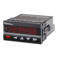
Housing: Panel-mount housing
to DIN 43 700, RAL 7021
Dimensions: 96 x 48 x 102 mm
Panel cut-out: 92
+0,8
x 45
+0,6
mm
Installation depth: ca. 92 mm incl. terminals
Weight: ca. 180 g
Protection: IP 65 (front, device only)
Housing material: Polycarbonate UL94 V-2
Vibration resistance: 10 - 55 Hz / 1 mm / XYZ
EN 60068-2-6 30 min. in each direction
Shock resistance:
EN 60068-2-27 100G / XYZ
3 times in each direction
EN 60068-2-29 10G / 6 ms/ XYZ
2000 times in each direction