S-39
05-E3B, 05-E3BG, WSM
DIESEL ENGINE
Injection Pump
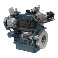
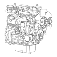
1. Disconnect the start spring (4) on the thrust lever side (5).
2. Align the control rack pin (2) with the notch (1) on the crankcase,
and remove the injection pump (3).
3. Remove the injection pump shims.
4. In principle, the injection pump should not be disassembled.
(When reassembling)
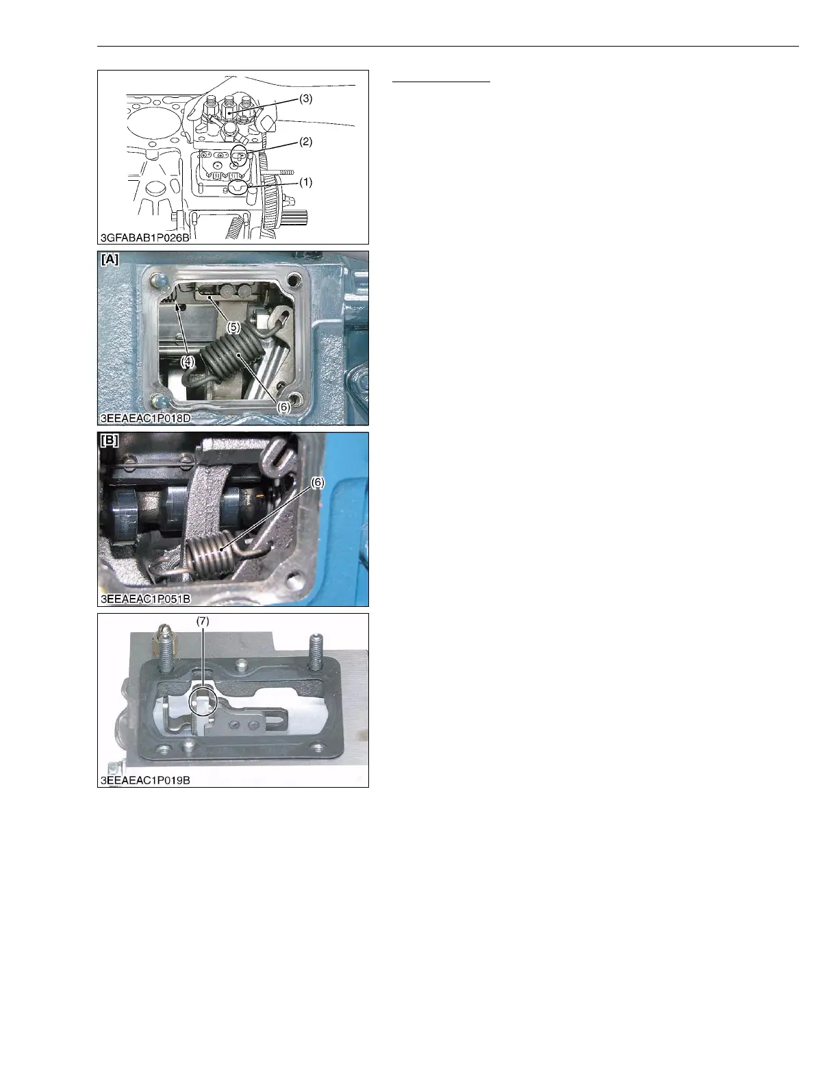
• When installing the injection pump, insert the control rack pin (2)
firmly into the groove (7) of the thrust lever of fork lever.
• Addition or reduction of shim (0.05 mm, 0.0020 in.) delays or
advances the injection timing by approx. 0.0087 rad (0.5 °).
• In disassembling and replacing, be sure to use the same
number or new gasket shims with the same thickness.
W1147317
(1) Notch
(2) Control Rack Pin
(3) Injection Pump
(4) Start Spring
(5) Thrust Lever
(6) Governor Spring
(7) Groove
[A] Basic Model
[B] BG Model
 Loading...