- 12 -
To facilitate transportation, a certain number of parts are not fitted to the
machine.
To fit these, proceed as follows :
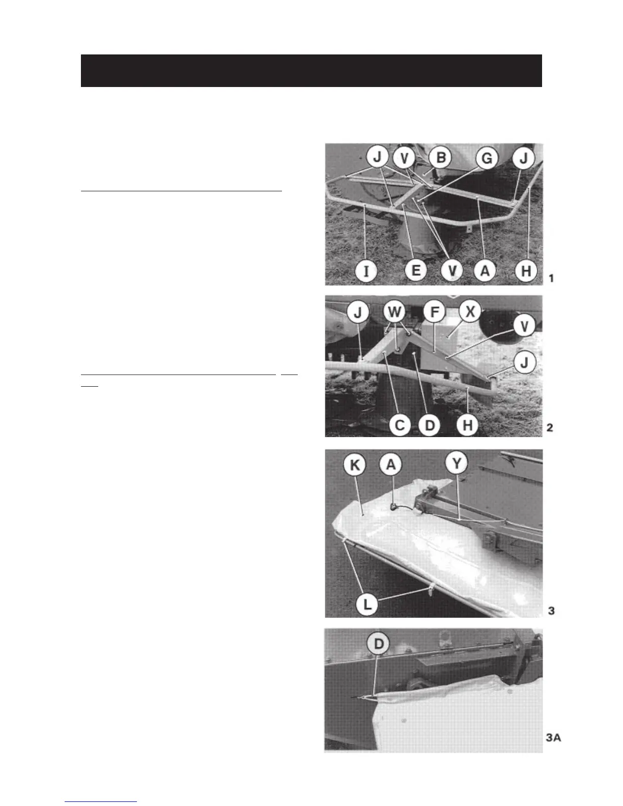
Assembly of guards (photos 1 and 2)
- Mount bar (A) to tube (B) and the
support arm (C) to drive tube (D).
- Secure the outer support (E) to bar (A)
and the inner support (F) to the support
arm (C) and guard (X).
- Mount the tie rod (G) to outer support
(E) and tube (B) as shown in photo 1.
V = screw M12x25 + washer + nut M12
W = screw M12x25 + washer
- Fit the front guard (H) and side guard
(I) using 5 special screws M10 x 25 +
washer 11 x 24 x 2, + self-locking nut
M10 as shown in photos 1 and 2.
Assembly of safety covers (photos 3 and
3A)
Unroll cover (K) and secure to the guard
tubes using straps (L) (photo 3).
Fit cord (Y). To do this, attach one end
of cord to the end of sliding lock (B)
(photo 4), thread through the eyelets
and attach handle (A) to the other end
(thread the cord through the handle and
tie a knot (photo 3).
Next attach safety covers together using
strap (E) (see photo 27 and fig. 28 on
page 18) and hook tensioner (D) on both
side shields as shown in photo 3A.
ASSEMBLY INSTRUCTIONS



 To Next Page