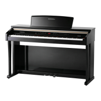
Mark Pro TWOi
22
Caution: Each switch button cap uses a set of small pegs to mount the cap to the Front Panel
Board. The button caps are mounted individually or in clusters. If a cap becomes
separated from the board, be careful that a peg is not inadvertently broken.
Replacing the Front Panel Board
1. Position the Front Panel Board onto the top enclosure, then raise the top enclosure up
slightly to verify that the volume slider and switch button caps are correctly positioned
through their openings in the top enclosure.
2. Align the center screw holes of the three-hole groupings on the front panel edge of the
board with the thread marks in the extrusion and install the two screws that secure the
front panel edge. See Figure 4-8.
3. Connect ribbon cable cables in the following order.
Caution: Be sure to look for the marking on the edge of the cable denoting Pin 1 and that you
inserting them into the connector and that each wire is correctly inserted into its
respective position.
connector.
.
4. If you have disconnected the
fl
at ribbon cable from J4, J5, reconnect it. Be sure to install the
cable locking clip.
Removing the Engine Board
1. Following Step 2, disconnect the cables listed in Table 4-4.
Ref. Name Cable Type Destination
J6
Mark Pro 2i
PWR
stranded wire
Amp Board
standard wire
Table 4-4 Engine Board cables
2. Disconnect the stranded wire cables from J6 to J10.

 Loading...