EasyManuals Logo

KVH Industries TracVision 4 User Manual

KVH Industries TracVision 4
73 pages
To Next Page IconTo Next Page
To Previous Page IconTo Previous Page
Page #17 background imageLoading...
Page #17 background image
2-6
A Guide to TracVision 4
You are now ready to wire the TracVision 4 system to the
switchplate connectors and ship’s power.
Tips for Safe and Successful Wiring
When attaching cables to the TracVision 4
switchplate connectors, make sure the insulation is
stripped back approximately
3
16". Twist the wires
gently to help achieve a good connection. Do not
pinch insulation inside the connector.
After attaching the power and data cables to the
appropriate terminal connector strips, tug gently
to ensure a firm connection.
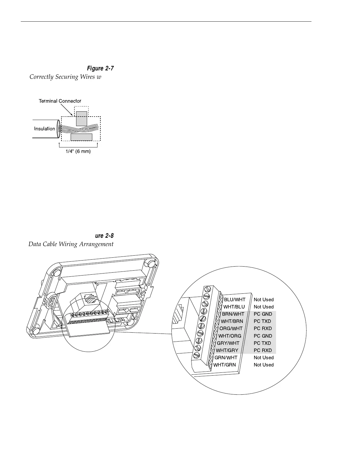
2.3.1 Wiring the Antenna Unit Data Cable
Find the TracVision 4 data cable (cable #32-0619-50) where it
comes through the panel cutout made earlier. Wire the data cable
to the switchplate connectors as indicated in Figure 2-8. The
connector board is etched with the same wire color identification
to make the wiring process easier.
A comprehensive wiring diagram for the TracVision 4 system has
been provided in Appendix D.
Insulation
Terminal Connector
1/4" (6 mm)
Figure 2-7
Correctly Securing Wires within
the Switchplate Connectors
BLU/WHT Not Used
WHT/BLU Not Used
BRN/WHT PC GND
WHT/BRN PC TXD
ORG/WHT PC RXD
WHT/ORG PC GND
GRY/WHT PC TXD
WHT/GRY PC RXD
GRN/WHT Not Used
WHT/GRN Not Used
Data Cable
to Antenna
(32-0619-50)
Figure 2-8
Data Cable Wiring Arrangement

Table of Contents

Other manuals for KVH Industries TracVision 4

Questions and Answers:

Question and Answer IconNeed help?

Do you have a question about the KVH Industries TracVision 4 and is the answer not in the manual?

KVH Industries TracVision 4 Specifications

General IconGeneral
BrandKVH Industries
ModelTracVision 4
CategorySatellite TV System
LanguageEnglish

Related product manuals