4. Installation of the replacement assembly is the
reverse of this. Reinstall all Molex connectors
removed in Step 1.
5. Calibrate the Gyro and LNB as described in
Sections 5.5 and 5.7.
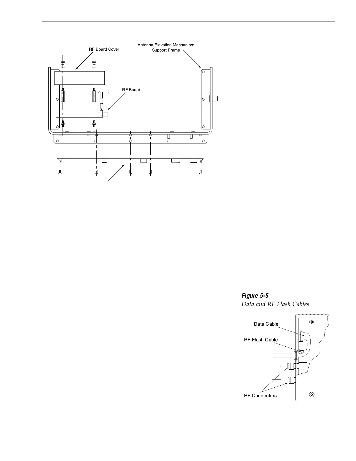
5.4.2 RF Detector
The RF Detector receives operating voltages from both the CPU
board and the IRD (via the RF cable). Ensure that all power
(including the IRD) is turned off before proceeding.
1. Use a
5
⁄16
" (8 mm) socket to remove the four nuts
and washers securing the RF Board cover. Set the
hardware and cover aside.
2. Cut the tie-wrap securing the Data and RF Flash
cables (pictured in Figure 5-5) to the RF Board.
3. Unplug the Data and RF Flash cables from the
RF Board.
4. Observe which RF cable is attached to the top RF
connector. If the top RF cable is not already
marked with yellow tape, add a piece of tape or
some identifying mark so that the RF cables can be
plugged into the proper RF connectors on the new
RF Board.
5-5
Maintenance
54-0150 Rev. D
Figure 5-4
PCB Mounting (Top View)

 Loading...


