The Antenna Unit printed circuit boards, Antenna LNB, elevation
stepping motor, and elevation drive belt may be removed and
replaced on site using common hand tools. Other TracVision 4
service must be done by your authorized dealer/installer or at
the factory. Evidence of tampering with or unauthorized repairs
will void the warranty. The following are step-by-step procedures
for removing and replacing those components that may be
serviced.
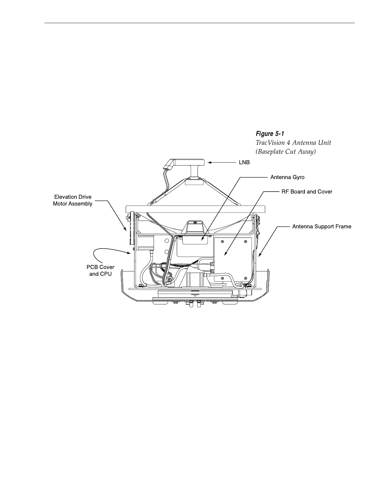
Figure 5-1 depicts the location of a number of components within
the TracVision 4 Antenna Unit.
5.4 PCB Removal and Replacement
The printed circuit boards (PCBs) are protected by a cover
fastened to the antenna support frame. The cover must be
removed to gain access to the main power fuse and the
PCB assemblies discussed below. Refer to Figure 5-2 on the
following page; remove (3) nuts and washers from the bottom
flange and (4) screws, nuts and washers from the upper flange.
Remove the cover and set aside with the fasteners.
5-3
Maintenance
54-0150 Rev. D

 Loading...


