2-7
54-0150 Rev. D
2.3.2 Wiring the Antenna Unit Power Cable
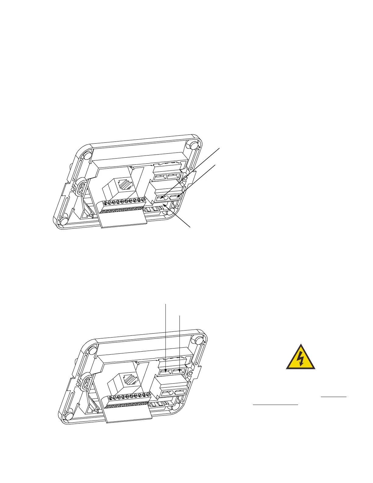
Find the TracVision 4 power cable (cable #32-0510-50) where it
comes through the panel cutout made earlier. Wire the antenna
unit power cable to the switchplate connectors as indicated in
Figure 2-9. After wiring the power cable, connect the power
indicator lamp, also as noted in Figure 2-9. After both the power
cable and lamp are properly wired, carefully insert the lamp into
its socket immediately below the switchplate connectors.
2.3.3 Connecting to Ship’s Power
After completely wiring the indicator lamp and the data and
antenna cables, you must connect the switchplate to ship’s power
as pictured in Figure 2-10.
Installation
Power supplied to the TracVision 4
MUST NOT exceed 16 Vdc or the
TracVision power supply will suffer
serious damage!
Figure 2-10
Wiring the Switchplate
to Ship’s Power

 Loading...


