EasyManuals Logo

KVH Industries TracVision 4 User Manual

KVH Industries TracVision 4
73 pages
To Next Page IconTo Next Page
To Previous Page IconTo Previous Page
Page #21 background imageLoading...
Page #21 background image
1. Connect the RF cable tagged "RF1" to the
multiswitch input labeled "LNB RHCP +13V".
2. Connect a second RF cable to the multiswitch
input labeled "LNB LHCP +18V".
3. Connect the multiswitch outputs to individual IRD
inputs. Use RG-6 cable terminated with F-type
connectors for all RF connections. Terminate all
unused output connectors with 75 ohm DC blocks
(Channel Master #7184, Radio Shack #15-1259 or
equivalent).
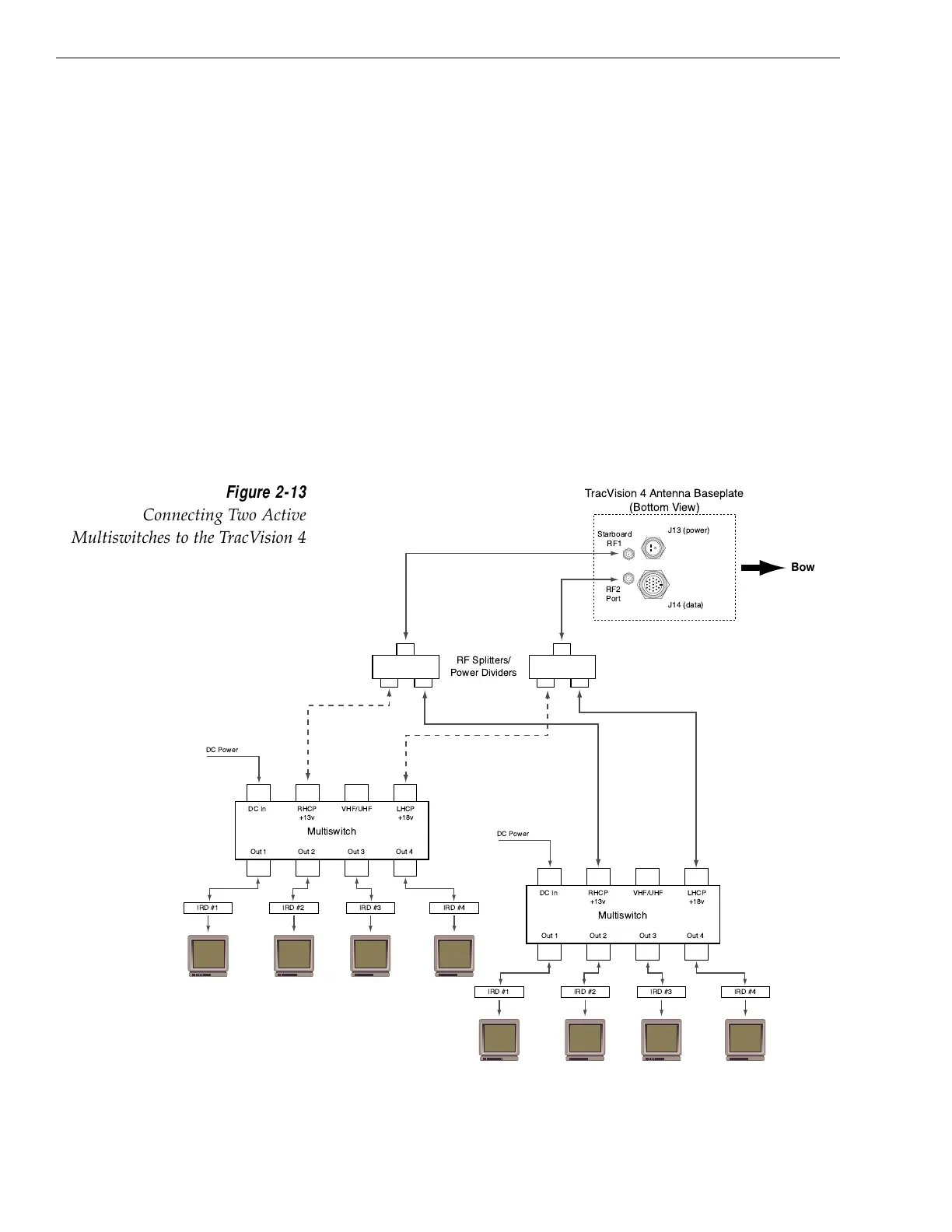
Multiple Multiswitch Installation
If there is a need for more than four IRDs, it is possible to
carry out a multiple multiswitch installation, as illustrated in
Figure 2-13.
2-10
A Guide to TracVision 4
Starboard
RF1
RF2
Port
J14 (data)
J13 (power)
TracVision 4 Antenna Baseplate
(Bottom View)
Multiswitch
DC In RHCP
+13v
VHF/UHF LHCP
+18v
Out 1 Out 2 Out 3 Out 4
DC Power
IRD #1 IRD #2 IRD #4IRD #3
Multiswitch
DC In RHCP
+13v
VHF/UHF LHCP
+18v
Out 1 Out 2 Out 3 Out 4
DC Power
IRD #1 IRD #2 IRD #4IRD #3
RF Splitters/
Power Dividers
Bow
Figure 2-13
Connecting Two Active
Multiswitches to the TracVision 4

Table of Contents

Other manuals for KVH Industries TracVision 4

Questions and Answers:

Question and Answer IconNeed help?

Do you have a question about the KVH Industries TracVision 4 and is the answer not in the manual?

KVH Industries TracVision 4 Specifications

General IconGeneral
BrandKVH Industries
ModelTracVision 4
CategorySatellite TV System
LanguageEnglish

Related product manuals