- 10 -
- 11 -
KVM6000
Operation and display
KVM6000
Faults and solutions
Digital
input
1. Optocoupler coupling isolation, compatible with dual
polarity input
2. Impedance: 2.4kΩ
3. Voltage range for level input: 9V-30V
4. S8 can be used for high-speed pulse input.
Maximum input frequency: 100kHz
S1-COM
Digital input 1
S3-COM
S2-COM
S4-COM
S5-COM
S6-COM
S7-COM
Digital input 3
Digital input 2
Digital input 4
Digital input 5
Digital input 6
Digital input 7
S8-COM
Digital input 8
Digital
output
Terminal
Commun-
ication
Function Description
Voltage or current output is decided by P5-32.
Output voltage range: 0V~10V
Output current range: 0mA~20mA
Contact driving capacity:
250Vac, 3A, COSØ=0.4.
30Vdc, 1A
AO1-GND
Y3-YC
Y4-YC
Y1A/Y1B/
Y1C
DA,DB
Y2A/Y2C
Name
Analog output
terminal 1
Relay digital
output 1
RS485 interface
Relay digital
output 2
Digital output
termianl 1
Digitaloutput
termianl 2
Type
Analog
output
1.Optocoupler coupling isolation, dual polarity open
collector output:
2.Output voltage range: 0~24 V
3.Output current range: 0
~50 mA
4.Y4 is limited by F5-32 “HDO function enable”. As high-
speed pulse output, the maximumfrequency is 50 kHz.
5.Select whether YC terminal and COM terminal are
electrically connected through SW1.
1. Standard RS485 communication interface;
2. Select whether to connect 120Ω termination resistor
through SW2.
AO2-GND
Analog output
terminal 2
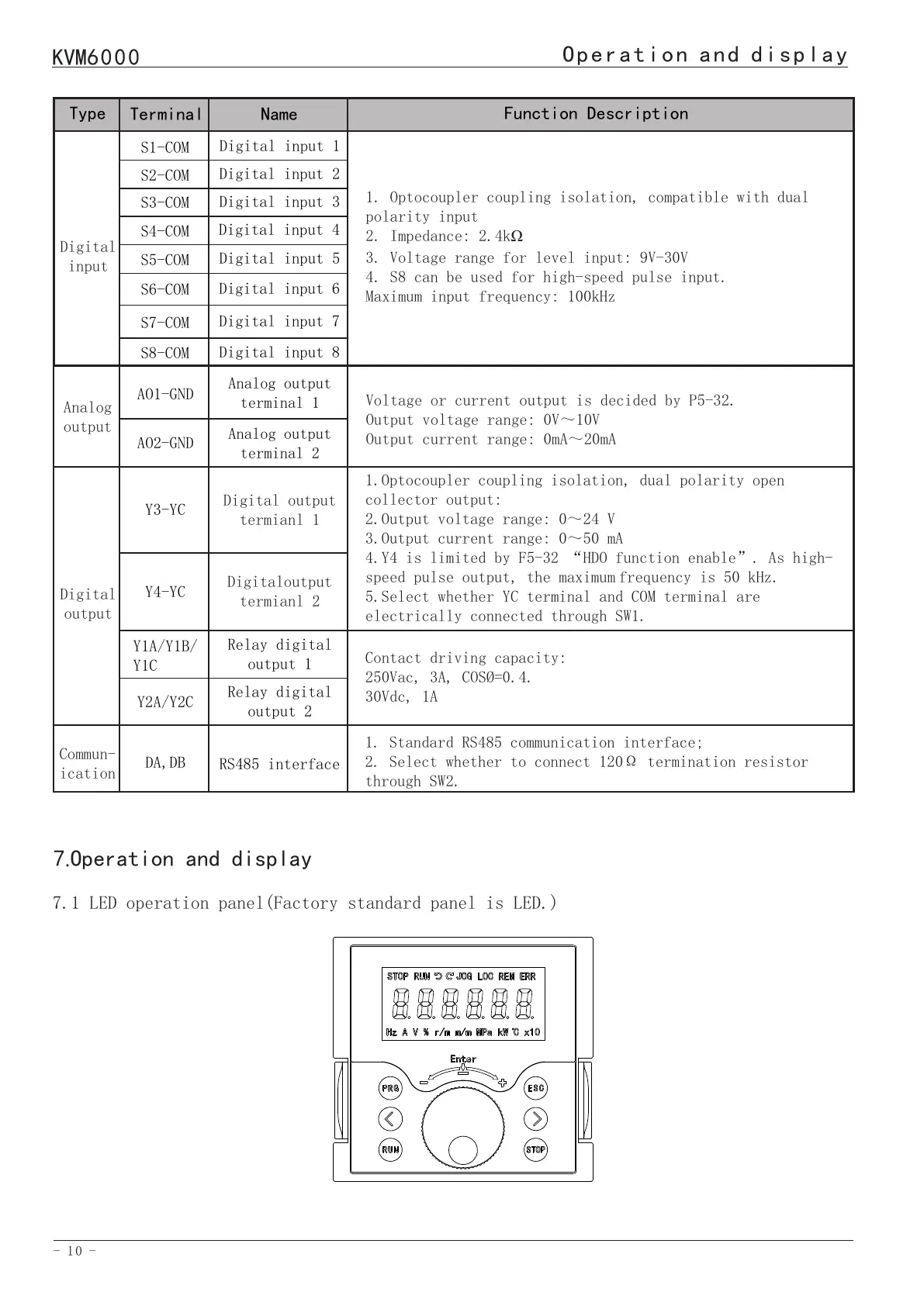
7.1 LED operation panel(Factory standard panel is LED.)
7.Operation and display
7.2 Description of LED operation panel indicators
Indicator
STOP
JOG
REM
Hz
V
r/m
MPa
Indicator
RUN
LOC
ERR
A
%
Kw
℃
Description
motor STOP
motor reverse rotation
JOG state
control mode set by the source of A03
monitoring interface is frequency
monitoring interface is voltage
monitoring interface is motor speed
monitoring interface is MPa under
monitor mode setting
Description
motor RUN
motor forward rotation
control source as panel
AC drive has failure
monitoring interface is current
monitoring interface for percentage
display
monitoring interface is power
monitoring interface is temperature
7.3 Description of Keys on the LED operation panel
PRG
</>
RUN
STOP
Key
Programming Set parameters
Move left and right function keys
RUN key Forward RUN(FRD)
STOP key
Function
Number INCREASE/DECEREASE and ENTER key
Exit and fault reset function
ESC
8.Faults and solutions
Display
Err01
Err02
Fault
name
Inverter unit
protection
Overcurrent
during
acceleration
Possible causes
1: The output circuit is grounded
or short circuited.
2: The power cable between the
motor and the AC drive is too
long.
3: The power module is overheated.
4: The internal connections
become loose.
5:The main control board is
faulty.
6: The drive board is faulty.
7: The inverter module is faulty.
1: The output circuit is grounded
or short circuited.
2: Motor auto-tuning is not
performed.
3: The acceleration time is too
short.
Solutions
1: Eliminate external faults.
2: Install a reactor or an output filter.
3: Check the air filter and the cooling
fan.
4: Connect all cables properly.
5: Seek technical support.
6: Seek technical support.
7: Seek technical support.
1: Eliminate external faults.
2: Perform the motor auto-tuning.
3: Increase the acceleration time.
 Loading...