- 38 -
- 39 -
- 27 -
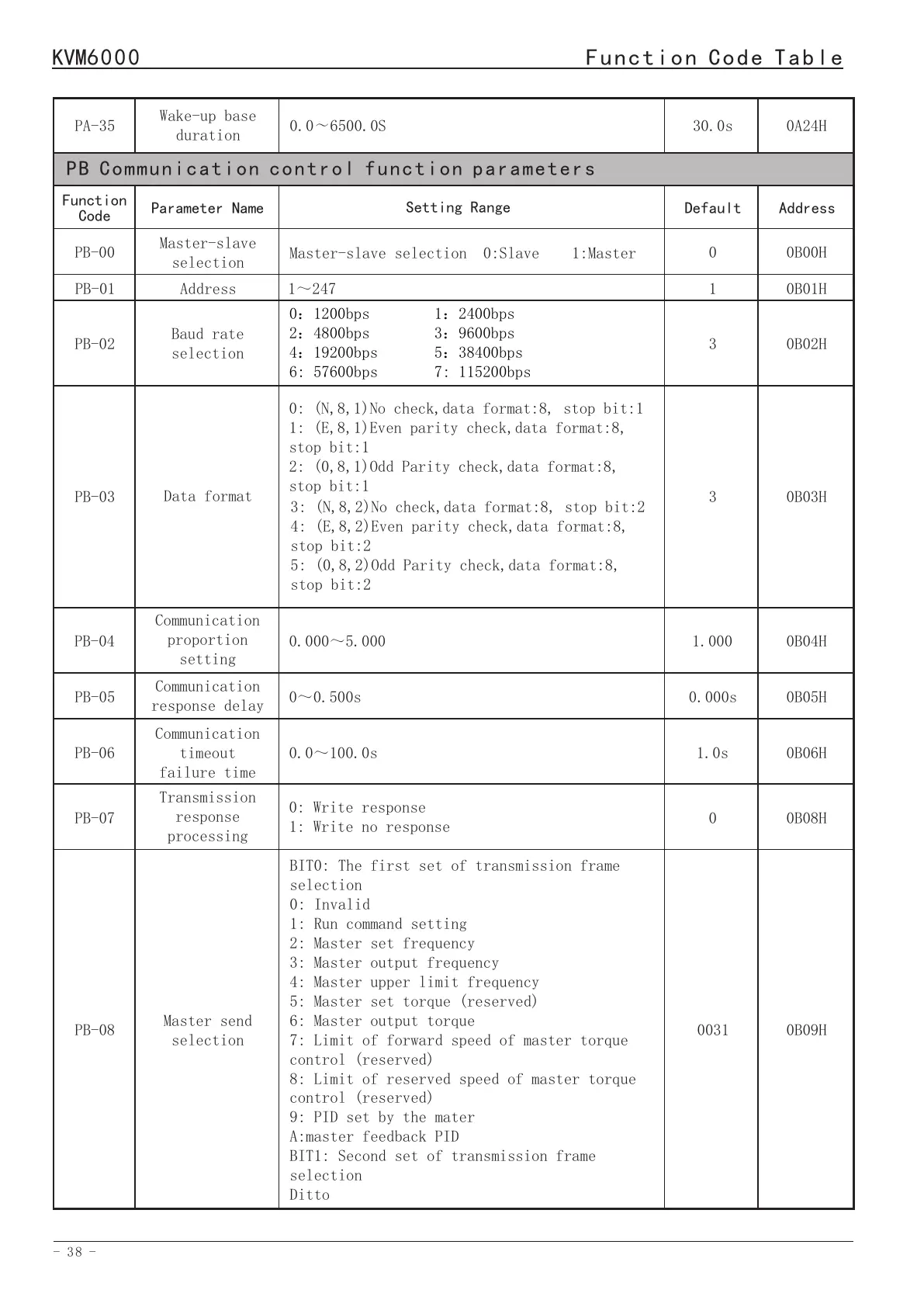
KVM6000
Function Code Table
KVM6000
Function Code Table
0.0~6500.0S
PA-35
Wake-up base
duration
30.0s
0A24H
PB Communication control function parameters
PB-00
PB-01
PB-02
Function
Code
Master-slave
selection
Address
Baud rate
selection
Parameter Name
Master-slave selection 0:Slave 1:Master
1~247
0:1200bps 1:2400bps
2:4800bps 3:9600bps
4:19200bps 5:38400bps
6: 57600bps 7: 115200bps
Setting Range
0
1
3
Default
0B00H
0B01H
0B02H
Address
PB-03
Data format
30B03H
PB-04
PB-05
PB-06
PB-07
Communication
proportion
setting
Communication
response delay
Communication
timeout
failure time
Transmission
response
processing
0: (N,8,1)No check,data format:8, stop bit:1
1: (E,8,1)Even parity check,data format:8,
stop bit:1
2: (0,8,1)Odd Parity check,data format:8,
stop bit:1
3: (N,8,2)No check,data format:8, stop bit:2
4: (E,8,2)Even parity check,data format:8,
stop bit:2
5: (0,8,2)Odd Parity check,data format:8,
stop bit:2
0.000~5.000
0~0.500s
0.0~100.0s
0: Write response
1: Write no response
1.000
0.000s
1.0s
0
0B04H
0B05H
0B06H
0B08H
BIT0: The first set of transmission frame
selection
0: Invalid
1: Run command setting
2: Master set frequency
3: Master output frequency
4: Master upper limit frequency
5: Master set torque (reserved)
6: Master output torque
7: Limit of forward speed of master torque
control (reserved)
8: Limit of reserved speed of master torque
control (reserved)
9: PID set by the mater
A:master feedback PID
BIT1: Second set of transmission frame
selection
Ditto
PB-08
Master send
selection
0031
0B09H
PB-08
Master send
selection
BIT2: The third set of transmission frame
selection
Ditto
BIT3: Selection of the fourth set of trans-
mission frames
Ditto
0031
0B09H
Address
0C00H
0C01H
Default
0000
12.00Hz
Function
Code
PC-00
PC-01
PC Optimization Parameters
Setting Range
BIT0: 0:Temperature independent
1:Temperature related
BIT1: 0:Asynchronous modulation
1: Synchronous modulation
BIT2:0: Random PWM invalid
1-A:Random PWM
BIT3:Reserved
0~15.00Hz
Parameter Name
Carrier frequency
characteristic
selection
DPWM switchover
frequency
upper limit
0C08H
0C09H
0C0AH
0C0BH
0C0CH
0C02H
0C03H
0C04H
0C05H
0C06H
0C07H
100%
0
2.0s
0
3.00S
1
1
1
10
100.0%
810.0V
PC-08
PC-09
PC-10
PC-11
PC-12
PC-02
PC-03
PC-04
PC-05
PC-06
PC-07
50~100%
0: Fault
1: Continue to operate within the allowable
time of undervoltage recovery
2: Continue to operate after the power supply
returns to normal
0.160.0s~
0: Invalid 1: Valid
0.0120.00s~
0: The operation of the fan isjust related to
the temperature
1: The operation is related to the temperature,
and during run, the fan is operating.
0~1
0~2
0~100
115.0~140.0%
0~2500.0V
Undervoltage
threshold
Solution of
undervoltage
fault
Allowable time
of undervoltage
recovery
Restart method
after power
failure
Waiting time
for restart
after power
failure
Cooling fan
control
Rapid current
limit enable
Dead zone
compensation mode
Current detection
compensation
Action voltage of
energy consumption
braking
Overvoltage
threshold