- 14 -
- 15 -
KVM6000
Faults and solutions
KVM6000
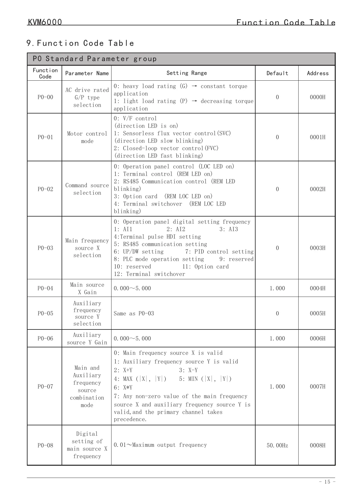
9.Function Code Table
P0 Standard Parameter group
0000H
Address
Function
Code
P0-00
AC drive rated
G/P type
selection
Setting Range
0: heavy load rating (G) → constant torque
application
1: light load rating (P) → decreasing torque
application
P0-01
P0-02
P0-03
P0-05
P0-04
P0-07
Command source
selection
Auxiliary
frequency
source Y
selection
Motor control
mode
Main frequency
source X
selection
Main source
X Gain
Main and
Auxiliary
frequency
source
combination
mode
0001H
0002H
0003H
0005H
0004H
0007H
0: V/F control
(direction LED is on)
1: Sensorless flux vector control(SVC)
(direction LED slow blinking)
2: Closed-loop vector control(FVC)
(direction LED fast blinking)
0: Operation panel control (LOC LED on)
1: Terminal control (REM LED on)
2: RS485 Communication control (REM LED
blinking)
3: Option card (REM LOC LED on)
4: Terminal switchover (REM LOC LED
blinking)
0: Operation panel digital setting frequency
1: AI1 2: AI2 3: AI3
4:Terminal pulse HDI setting
5: RS485 communication setting
6: UP/DW setting 7: PID control setting
8: PLC mode operation setting 9: reserved
10: reserved 11: Option card
12: Terminal switchover
Same as P0-03
0.000~5.000
0:Main frequency source X is valid
1:Auxiliary frequency source Y is valid
2:X+Y 3:X-Y
4:MAX(|X|,|Y|) 5:MIN(|X|,|Y|)
6:X*Y
7:Any non-zero value of the main frequency
source X and auxiliary frequency source Y is
valid,and the primary channel takes
precedence.
Default
0
0
0
0
1.000
0
Auxiliary
source Y Gain
P0-060006H
0.000~5.000
1.000
1.000
Parameter Name
0008HP0-08
Digital
setting of
main source X
frequency
0.01~Maximum output frequency
50.00Hz
Function Code Table
Err20
Err21
Err22
Encoder
fault
EEPROM
readwrite fault
AC drive
hardware fault
3: The encoder is damaged.
4: The PG card is faulty.
1: The EEPROM chip is damaged.
1: Overvoltage exists.
2: Overcurrent exists.
3: Replace the damaged encoder.
4: Replace the faulty PG card.
1: Replace the main control panel.
1: Handle based on over-voltage.
2: Handle based on over-current.
Err23
Short circuit
to ground
1: The motor is short circuited
to the ground.
1: Replace the cable or motor.
Err24
Err26
EEPORM
Initialization
fault
1: Abnormal user data.
1: Reinitialize data and set
parameters.
Running
time reached
1: Accumulative running time
reaches setting.
1: Clear the record through the
parameter initialization function.
Err29
Power-on time
reached
Err30
1: Accumulative power-ontime
reaches the setting.
1: The AC drive running current
is lower than P9-38.
1: Clear the record through the
parameter initialization function.
1: Check the load is disconnected or
P9-38 and P9-39 is correct.
Load
becoming 0
Err27
Err28
User-defined
fault 1
User-defined
fault 2
1: The user-defined fault 1 signal
is input via DI.
1: Reset the operation.
Err31
Err40
PID feedback
lost during
running
Pulse-by-pulse
current
limit fault
1: The PID feedback is lower than
the setting of PA-27.
1: The load is too heavy or
lockedrotor occurs on the motor.
2: The AC drive model is of too
small power class.
1: Check the PID feedback signal or
set PA-27 to a proper value.
1: Reduce the load and check the
motor and mechanical condition.
2: Select the AC drive of higher
power class.
Err42
Err43
Too large
speed
deviation
Motor
over-speed
1: The encoder parameters are set
incorrectly.
2: The motor auto-tuning is not
performed.
3: P9-42 and P9-43 are set
incorrectly.
1: The encoder parameters are set
incorrectly.
2: The motor auto-tuning is not
performed.
3: P9-40 and P9-41 are set
incorrectly
1: Set the encoder parameters
properly.
2: Perform the motor autotuning.
3: Set F9-69 and F9-70 correctly
based on the actual situation.
1: Set the encoder parameters
properly.
2: Perform the motor auto-tuning.
3: Set P9-40 and P9-41 correctly
based on the actual situation.
Err45
Err51
Motor
overheat
Pole position
detection
failed
1: The cabling of the temperature
sensor becomes loose.
2: The motor temperature is too
high.
1: The deviation between the motor
parameters and the actual value is
too large.
1: Check the temperature sensor
cabling and eliminate the cabling
fault.
2: Lower the carrier frequency or
adopt other heat radiation measures.
1: Reconfirm whether the motor
parameters are correct, and focus on
whether the rated current is set too
small.
 Loading...