- 30 -
- 31 -
KVM6000
Function Code Table
KVM6000
Function Code Table
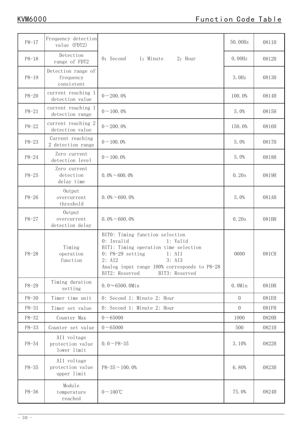
current reaching 1
detection value
current reaching 1
detection range
P8-20
P8-21
0:Second 1:Minute 2:Hour
0~200.0%
0~100.0%
100.0%
5.0%
0814H
0815H
Frequency detection
value (FDT2)
P8-17
50.00Hz
0811H
Detection
range of FDT2
P8-18
0.00Hz
0812H
P8-19
3.0Hz
0813H
Detection range of
frequency
consistent
P8-22
0~200.0%
150.0%
0816H
current reaching 2
detection value
P8-23
P8-26
P8-29
Current reaching
2 detection range
Output
overcurrent
threshold
Timing duration
setting
0~100.0%
0.0%~600.0%
0.0~6500.0Min
5.0%
5.0%
0.0Min
0817H
081AH
081DH
P8-24
Zero current
detection level
0~100.0%
5.0%
0818H
P8-25
Zero current
detection
delay time
0.0%~600.0%0.20s
0819H
P8-27
Output
overcurrent
detection delay
0.0%~600.0%0.20s
081BH
P8-28
Timing
operation
function
BIT0: Timing function selection
0: Invalid 1: Valid
BIT1: Timing operation time selection
0: P8-29 setting 1: AI1
2: AI2 3: AI3
Analog input range 100% corresponds to P8-28
BIT2: Reserved BIT3: Reserved
0000
081CH
P8-300
081EH
Timer time unit
0: Second 1: Minute 2: Hour
P8-31
0
081FH
Timer set value
0: Second 1: Minute 2: Hour
P8-32
1000
0820HCounter Max
0~65000
P8-33500
0821H
Counter set value
0~65000
P8-34
3.10%
0822H
AI1 voltage
protection value
lower limit
0.0~P8-35
P8-35
6.80%
0823H
AI1 voltage
protection value
upper limit
P8-35~100.0%
P8-36
75.0%
0824H
Module
temperature
reached
0~100℃
BIT0:Motor overload protection selection
0:Invalid 1:Valid
BIT1:Ground fault duringpower-on
0:Invalid 1:Valid
BIT2:Input phase loss protection selection
0:Invalid 1:Valid
BIT3:Output phase loss protection selection
0:Invalid 1:Valid
1011
Protection
function
selection 1
P9-000900H
P9 Fault and protection parameters
Function
Code
Parameter Name
Setting Range
Default
Address
BIT0: Output load loss protection selection
0: Invalid 1: Deceleration 2: Ramp to stop
BIT1: Instantaneous power failure action
selection
0: Invalid 1: Valid
BIT2: Continue operation frequency selection
in case of failure
0: Operate at current operation frequency
1: Operate at set frequency
2: Operate at the upper limit frequency
3: Operate at the lower limit frequency
4: Operation at abnormal standby frequency
BIT3: Action selection of fault “DO”during
fault automatic reset
0: No action 1: Action
0000
Protection
function
selection 2
P9-010901H
P9-02
Fault auto
reset times
00902H
0: OFF
Automatic reset function is turned off, only
manual reset is allowed.
1-20: ON
This function is on, 1-20 is the number of
times of self recovery after failure (defined
as the maximum number of times of auto reset
after each failure)
P9-03
Time interval of
fault auto reset
0.01s0903H
0.1~100.0s
P9-04
1st
fault type
Read-only
0904H
1 -- ERROR_INVERTER UNIT
2 -- ERROR_OC_DURING_ACC
3 -- ERROR_OC_DURING_DEC
4 -- ERROR_OC_AT_CONST_SPEED
5 -- ERROR_OV_DURING_ACC
6 -- ERROR_OV_DURING_DEC
7 -- ERROR_OV_AT_CONST_SPEED
8 -- ERROR_CONTROL POWER SUPPLY
9 -- ERROR_UV
10 -- ERROR_OL_AC DRIVE
11 -- ERROR_OL_MOTOR
12 -- ERROR_LOSE_PHASE_INPUT
13 -- ERROR_LOSE_PHASE_OUTPUT
14 -- ERROR_OH_MODULE
 Loading...