- 48 -
- 49 -
KVM6000
Function Code Table
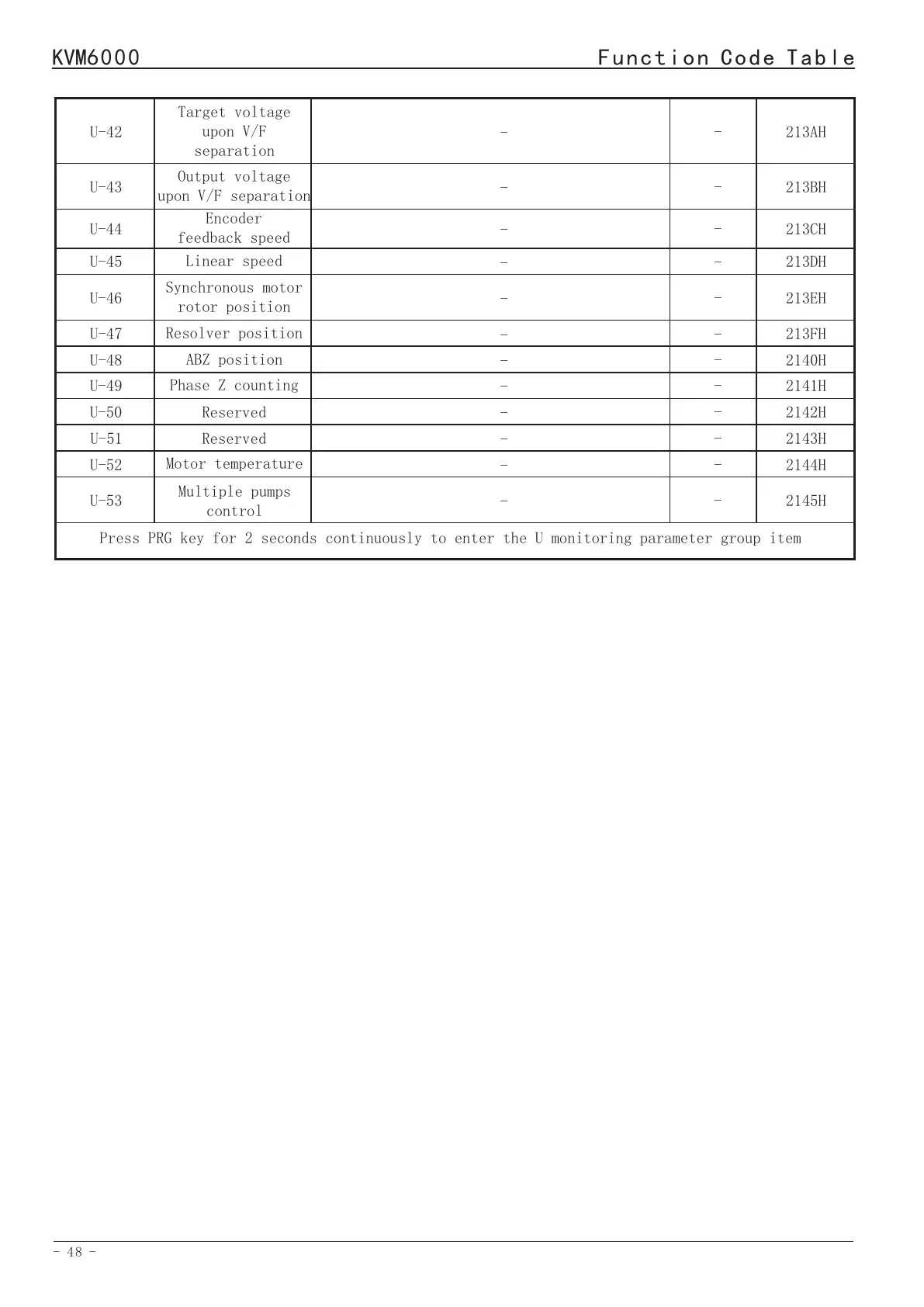
U-42
U-43
U-44
U-45
Target voltage
upon V/F
separation
Output voltage
upon V/F separation
Encoder
feedback speed
Linear speed
-
-
-
-
-
-
-
-
213AH
213BH
213CH
213DH
U-47
U-48
U-49
Resolver position
ABZ position
Phase Z counting
-
-
-
-
-
-
213FH
2140H
2141H
U-46
Synchronous motor
rotor position
-
-
213EH
U-50
-
-
2142H
Reserved
U-51
U-52
U-53
Reserved
Motor temperature
Multiple pumps
control
-
-
-
-
-
-
2143H
2144H
2145H
Press PRG key for 2 seconds continuously to enter the U monitoring parameter group item
10.Standard wiring diagram
KVM6000
Standard wiring diagram
External braking
resistor
External
DC reactor
Short
circuit
plate
Note4
AC
POWER
INPUT
Circuit
breaker
MCCB
Contactor
MC
Input
reactor
Output
reactor
A
N
A
L
O
G
I
N
P
U
T
(Ground resistance<10Ω)
Shielded cable
(Close to AC drive
ground terminal)
D
I
G
I
T
A
L
I
N
P
U
T
(Factory short circuit, 24V port
maximum output:DC24V/100mA)
Note2
(Forward RUN)
(Reverse RUN)
(Forward JOG)
(Reverse JOG)
(Coast to stop)
(Fault reset)
(Frequency up(UP))
(Frequency down(DW))
Note:1. The function in brackets descriptions
the factory value of AC drive;are
2. Opticalcoupler isolation, compatible
ambipolarity input;
3. Input impedance: 2.4kΩ;
4. Voltage range at electrical level input:
9V~30V
Shielded twisted pair
(Close to AC drive ground terminal)
Note:1. Maximum output current of 10V port:10mA,
resistance range of potentiometer:1KΩ~5KΩ;
2. Input voltage range of AI1 port:DC 0V~10V,
input impedance:22KΩ;
3. A12/AI3 port determines voltage or current
input by P5-00 function parameter, input range:
(0V~10V)/(0/4mA~20mA);input impedance:22KΩ
for voltage input,500Ω for current input.
Shielded twisted pair
(Close to AC drive ground terminal)
Legend:1. Symbol represents the main circuit terminal;
2. Symbol represents control circuit terminal.
High-speed
pulse output
Shielded twisted pair
(Close to AC drive ground terminal)
Coil
Coil
Shielded twisted pair
(Close to AC drive ground terminal)
Coil
Shielded twisted pair
(Close to AC drive ground terminal)
Coil
High-speed
pulse input
Note3
Note: The voltage or current output of AO1/AO2
port is determined by P5-32 function parameters,
and the output range is (0V~10V)/(0mA~20mA).
Note1
Note:Maximum output of Y1/Y2 port: AC250V/3A,
DC24V/5A;
Maximum output of Y3/Y4 port: DC24V/50mA.
D
I
G
I
T
A
L
I
N
P
U
T
A
N
A
L
O
G
I
N
P
U
T
R
R
S
T
R
S
T
-+
1
PR
+
2
U
V
W
U
V
W
M
~
24V
PLC
S1
S2
S3
S4
S5
S6
S7
S8
COM
10V
AI1
AI2
AI3
GND
AO1
A02
GND
GND
Y3
Y4
YC
PLC
AC200V
ACOV
ACOV
AC200V
Y1A
Y1B
Y1C
Y2A
Y2C
HDI
HDO
 Loading...