6-9
6
NOTE: If gears are being replaced, use the exist-
ing shims. The numbers are scribed onto the
gears: the ring gear has the number on the oppo-
site side of the gears, and the pinion gear has the
number on the end of the pinion gear shaft by the
splines. If no number is present, it should be con-
sidered as being in the 0 category.
NOTE: If the gear case housing is being replaced,
proceed to the following Shimming Proce-
dure/Shim Selection sub-section.
Shimming Procedure/Shim
Selection
1. Press bearings into bores by outer ring to hard con-
tact with seat.
2. Install the lock collar and tighten to 125 ft-lb; then
on final assembling, stake the lock collar edge
approximately 1.5 mm into the lower oil channel.
CC891
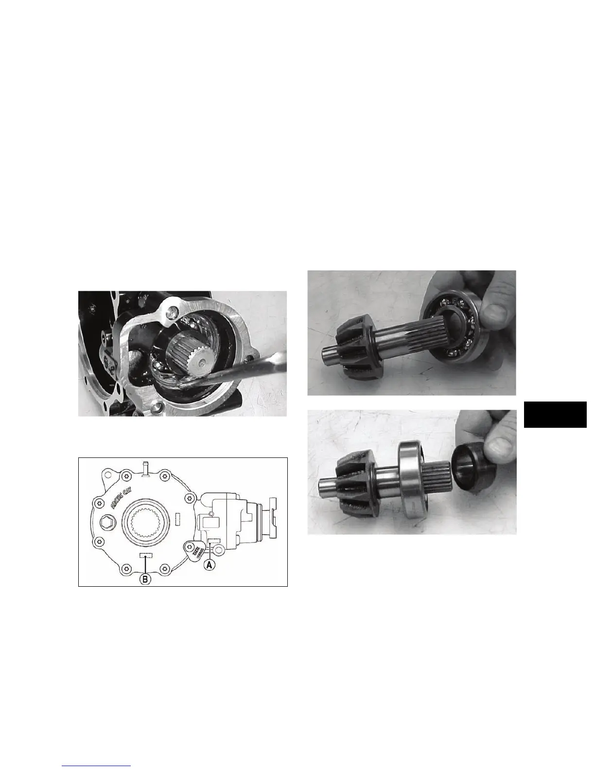
3. Note the following shim selections (shims are
nominally 1.5 mm thick):
738-268C
A. Cover Side - add value A on the gear case hous-
ing to value B on the gear case cover; then add
1.5 mm. This will give you the proper shim
thickness.
B. Gear Case Side - install a 1.3-1.4 mm shim and
tighten the bolts to 25-31 ft-lb. Verify backlash
to be within a range of 0.28-0.38 mm
(0.011-0.015 in.) and end-play to be within a
range of 0.10-0.20 mm (0.004-0.008 in.). If not
within specification range, reselect shim until
backlash specification range can be verified.
4. Prior to final assembling, apply molybdenum dis-
ulfide grease to all oil seal lips.
5. Prior to final assembling, prelubricate journal on
pinion assembly with SAE 80W-90 hypoid gear
lubricant prior to pressing assembly into gear case
housing.
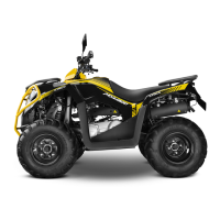
Assembling Pinion Gear
1. Install the bearing onto the pinion shaft. Install the
pinion shaft collar.
CC882
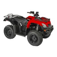
CC883
2. Place the pinion assembly in a bearing puller; then
install the bearing using a press.