LAARS Heating Systems
Page 32
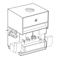
4.9 Gas Supply and Piping (continued)
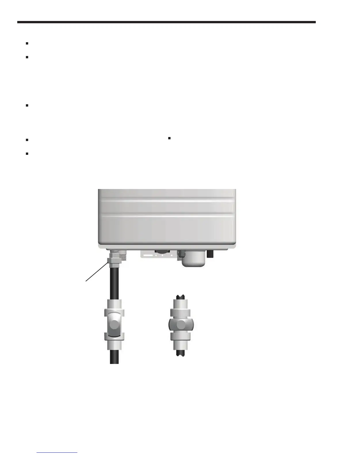
The gas connection tting on the unit is
3
/
4
˝
female NPT.
The supply line must be sized for the maximum
output of the boiler model being installed. If there
are additional gas appliances from the main
supply line, you must measure sizes of the supply
line according to the COMBINED total maximum
BTUH draw for the appliances as if they were all
operating at the same time.
Measure the length of the gas supply line from
the gas meter to the Boiler.
Use the tables in this manual or refer to the gas
line manufacturers sizing information to determine
the correct supply pipe size.
The gas shut-off valve in the gas supply line
should be installed close to the unit.
To facilitate any future maintenance, it is also
CLOSED POSITION
UNION FITTING
MANUAL SHUT OFF VALVE
GAS PIPE
recommended that an approved gas union tting
be installed in the supply line between the shut-off
valve and the
3
/
4
˝ female NPT connection on the
Boiler.
1) Install an approved gas line pipe to gas line
connection under the Boiler.
Include manual shut off valve and gas union
connection, as shown.
2) Test gas pressure to make sure it meets the
minimum standards and does not exceed the
maximum standards for the boiler.
3) Leak test the gas line pipe before placing the
unit in operation. Use approved leak detector
liquid solutions only to check for leaks.
Do Not Operate the boiler until all connections have
been completed, checked for leaks, and the heat
exchanger is lled with water.
Figure 8. Gas Line Valve Detail