DIP SWITCH S2
"NEPTIS/LE”
CONTROL UNIT
(to be set with
digital selector)
DIP SWITCH
SW1
PHOTOCELL
BOARD
DIP8 DIP9 DIP1 DIP2
OFF ON
OFF
ON
ON
ON
ON
OFF
ON
ON
OFF
ON
ON
OFF
OFF
ON
ON
ON
ON
ON
NUMBER OF PHOTOCELLS INSTALLED AND THEIR USE
1 CLOSING SAFETY PAIR (FT3/FR3)
1 PAIR AS OPENING CONTROL (FT1/FR1)
2 (FT1/FR1 & FT2/FR2)PAIRS AS OPENING CONTROL
1 (FT1/FR1)
and 1 CLOSING SAFETY PAIR (FT3/FR3)
PAIR AS OPENING CONTROL
2 (FT1/FR1 & FT2/FR2)
and 1 CLOSING SAFETY PAIR (FT3/FR3)
PAIRS AS OPENING CONTROL
OPERATING MODE OF THE PAIRS OF PHOTOCELLS
FT1/FR1: same operation as the INTERNAL RADAR input.
FT2/FR2: same operation as the EXTERNAL RADAR input.
FT3/FR3: safety photocell. Operates during the closing phase, by reversing the direction of the door.
TABLE 12.1
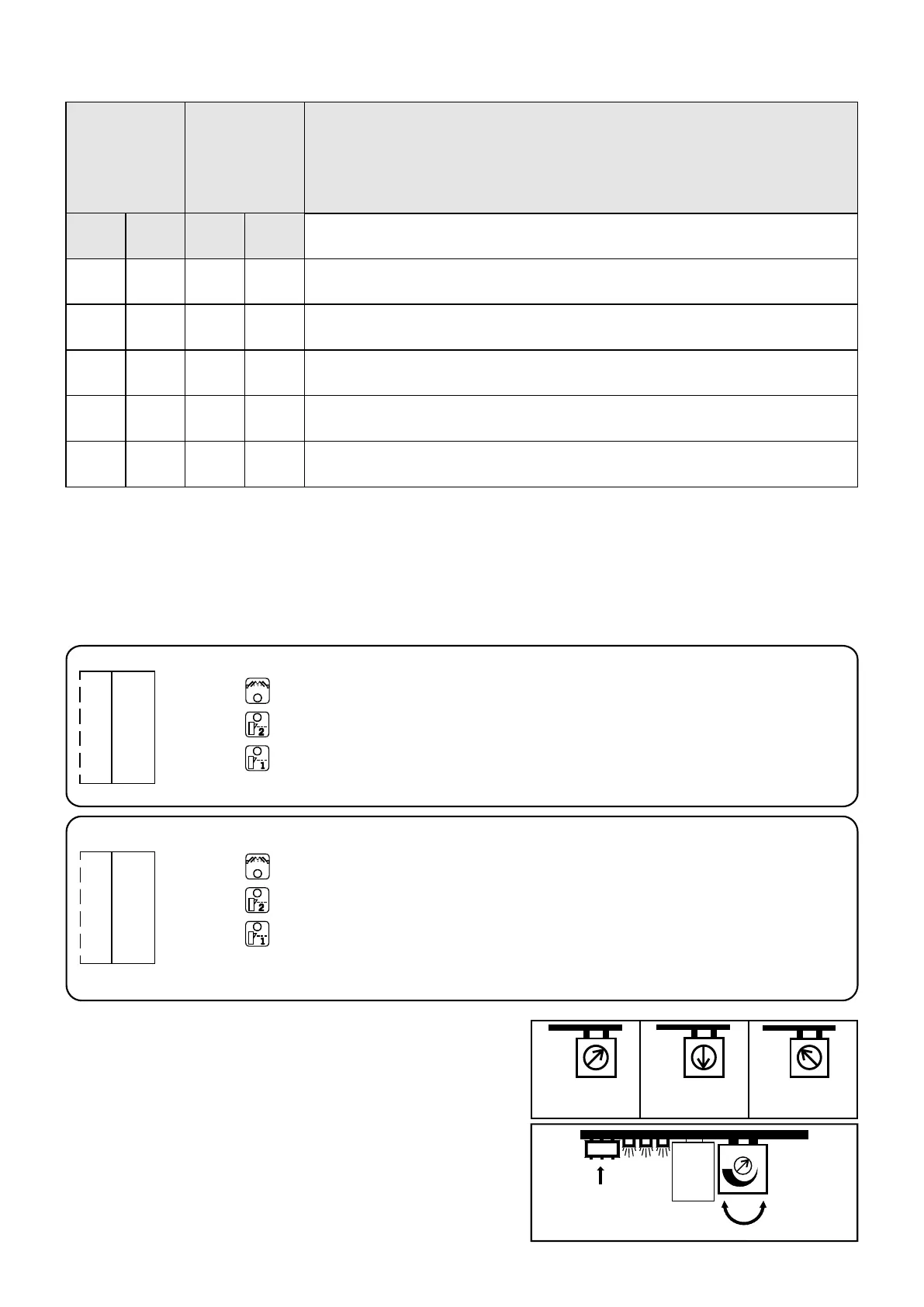
SENSITIVITY ADJUSTMENT
Once the pohotocells have been positioned, their sensitivity must be
regulated by means of the potentiometer on the board. Proceed in the
following way:
1) Calibrate the potentiometer depending on the distance between the
photocells (see figure alongside).
2) If the leds on the phtocells are off, their sensitivity is correct.
3) If the leds are on, slowly turn the potentiometer towards its maximum
setting until the leds go out.
4) Check to make sure that the relative leds come on by breaking the
infrared beam of the photocells.
MIN. POTENTIOM.
SETTING
up to 2 meters
POTENTIOMETER
HALFWAY
2 to 4 meters
MAX. POTENTIOM.
SETTING
4 to 6 meters
MIN
SENSITIVITY
MAX
SENSITIVITY
DIP SWITCH SW1
L1 L2 L3
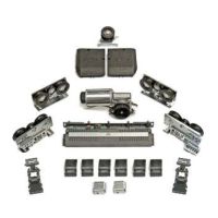
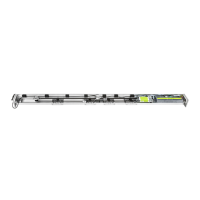
RECEIVER AND TRANSMITTER CONNECTIONS
To avoid interference due to direct sunlight, the receivers should be installed on the more sheltered side.
Terminal board M5 ( FT1 - FT2 - FT3- + )
FT3 = TRANSMITTER 3 input ( BLACK WIRE)
FT2 = TRANSMITTER 2 input ( BLACK WIRE)
FT1 = TRANSMITTER 1 input ( BLACK WIRE)
+ = POWER SUPPLY FOR ALL THE TRANSMITTERS (BLUE WIRES)
Terminal board M6 ( FR1 - FR2 - FR3- VCC - GND )
FR3 = RECEIVER 3 input (BROWN WIRE))
FR2 = RECEIVER 2 input (BROWN WIRE))
FR1 = RECEIVER 1 input (BROWN WIRE))
VCC = ( + ) POWER SUPPLY FOR ALL THE RECEIVERS (BLUE WIRES)
GND = ( - ) POWER SUPPLY FOR ALL THE RECEIVERS (BLACK WIRES)
FR3
FR2
FR1
VCC
GND
M6
FT3
FT2
FT1
+
M5
29

 Loading...