10 | HPI Combi Flow User Guide | Version 3.11 www.lafert.com
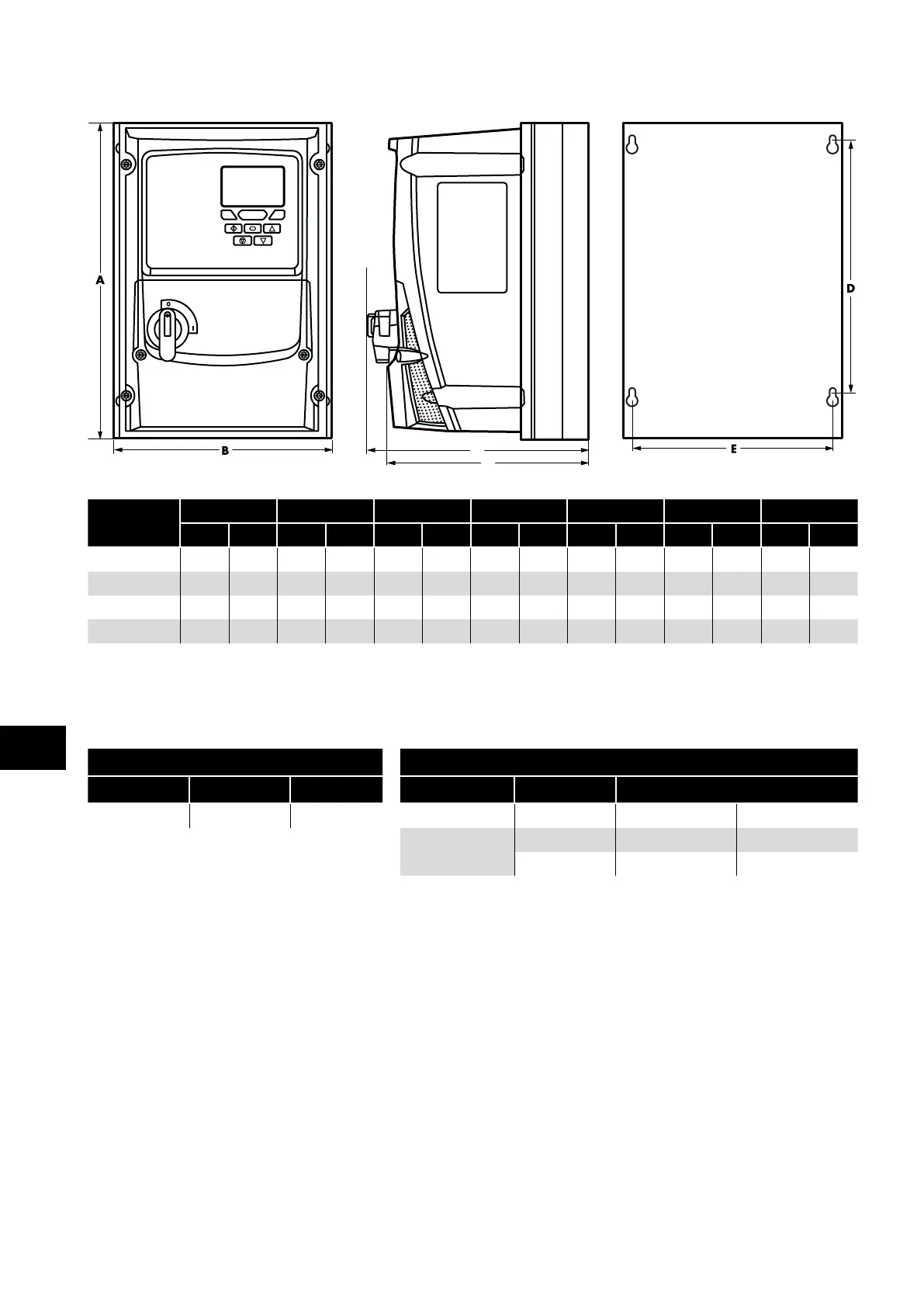
3.5.2. IP66 Units
C
Drive Size
A B C D E F Weight
mm in mm in mm in mm in mm in mm in kg Ib
2 257 10 .12 188 7.40 182 7.16 200 7. 87 178 7.00 172 6.77 5.5 12 .1
2A 257 10 .12 188 7.40 211 8.31 200 7. 87 178 7.00 19 6 7. 72
3 310 12.20 211 8.31 235 9.25 252
9.92
197 7. 75 225 8.86 8.5 18 . 7
4 360 14 .17 240 9.45 2 71 10.67 300 11 . 81 227 8.94 260 10.24 9.5 20.9
NOTE
Measurement C is only valid for the version with the disconnect.
Frame size 2A is shown for the 5.5kW Frame size 2 as this requires a deeper heatsink with a fan.
Mounting Bolts Tightening Torques
Frame Size Metric UNF Frame Size Required Torque
All Sizes M4 #8 Control Terminals 2, 3 & 4 0.5 Nm 4.5 lb-in
Power Terminals
2 & 3 0.8 Nm 7 lb-in
4 2 Nm 19 lb-in
3
Mechanical Installation