Version 3.11 | HPI Combi Flow User Guide | 25www.lafert.com
4.9. IP66 Switched Version Integrated Control Switch and Potentiometer Wiring
HP Combi Flow is optionally available with an integrated mains switch-disconnector and front mounted control switch and
potentiometer. This allows the drive to be operated directly from the front control panel, whilst also providing for options such as Hand
/ Auto or Local / Remote Control etc.
The integrated switch in IP66 Outdoor models operates in parallel with drive terminal 2 (T2) and terminal 3 (T3) as digital input 1 and
digital input 2. By default, the integrated switch is enabled.
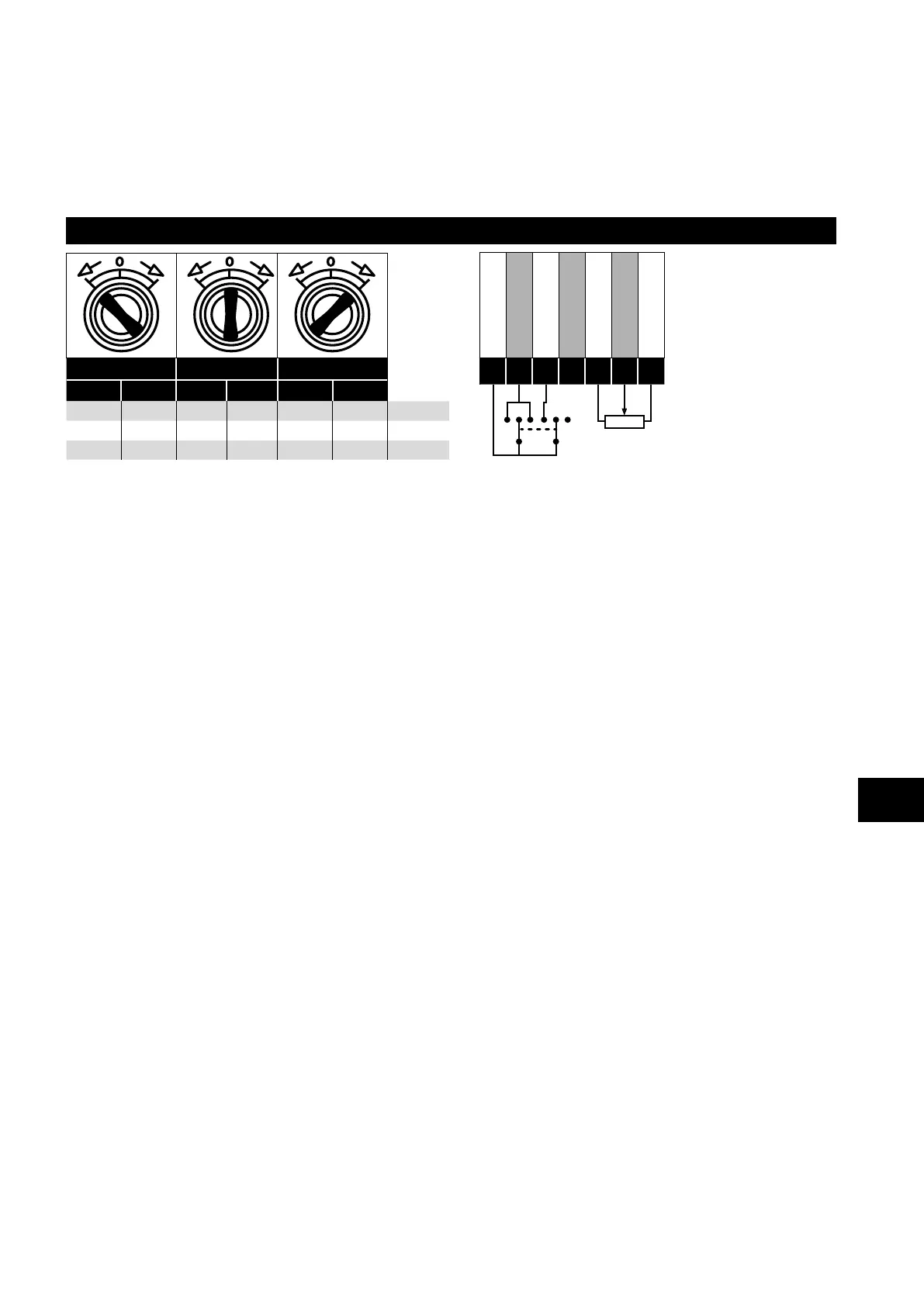
Integrated Control Switch and Potentiometer Wiring
Switch Left Switch Centre Switch Right
DI1 DI2 DI1 DI2 DI1 DI2
1 1 0 0 1 0 Lc-Off
0 0 0 0 0 0 Lc-On
0 1 0 0 1 0 Altern
+24V DC
DI 1
DI 2
DI 3
+10V DC
AI 1
0V / COM
1
2
3
4
5
6
7
4.9.1. Disabling built-in switches
If required, the built-in control switch may be disabled using the following method:
1) Ensure the drive is stopped (Display shows “Stop”).
2) Enable Advanced Parameter Access by setting the correct value in P1-14 (default : 201).
3) Scroll down to parameter P0-01 (Display shows P0-01).
4) Press and hold “STOP” button for >1s, drive will show:
IP66 Switch Setup
2: Pos >>DI1, Pos<<DI2
1: Switch disabled
0: Pos >>DI1, Pos <<DI1&2
5) Use “UP” or “DOWN” key to select the option:
0: Pos >>DI1, Pos <<DI1&2 means integrated switches are enabled.
1: Switch disabled means the switches are locked/disabled.
2: Pos >>DI1, Pos<<DI2 means that Revers direction is disabled via built-in switch (can be unlocked via external enable signal
connected to DI1 – terminal 2).
6) Press the “STOP” button again to exit.
4
Electrical Installation