24 | HPI Combi Flow User Guide | Version 3.11 www.lafert.com
4.7.4. Analog Outputs
Two analog outputs are available, and may be used for 0 – 10 Volt Signal (max load 20mA), 0 – 20mA, 4 – 20mA or a digital
+24Volt DC, 20mA output. The parameters to select function and format are as follows.
Analog Output Function selected by Format selected by
Analog Output 1 P2-11 P2-12
Analog Output 2 P2-13 P2-14
These parameters are described more fully in section 8.1. Digital Input Configuration Parameter P1-13 on page 38.
4.7.5. Auxiliary Relay Outputs
Two relay outputs are available, which are intended to be used to switch external resistive loads up to 5A at 230 VAC or 30VDC.
Relay 1 has both normally open and normally closed contacts available. Relay 2 provides a simple open or closed contact.
The relay output function may be configured using parameters P2-15 and P2-18, which are described in section 8.1. Digital Input
Configuration Parameter P1-13 on page 38.
4.8. Motor Thermal Overload Protection
4.8.1. Internal Thermal Overload Protection
HP Combi Flow has internal motor overload protection (current limit) set at 150% of FLC. This level may be adjusted using P4-07.
The drive has an in-built motor thermal overload function; this is in the form of an “I.t-trP” trip after delivering >100% of the value set in
P1-08 for a sustained period of time (e.g. 150% for 60 seconds).
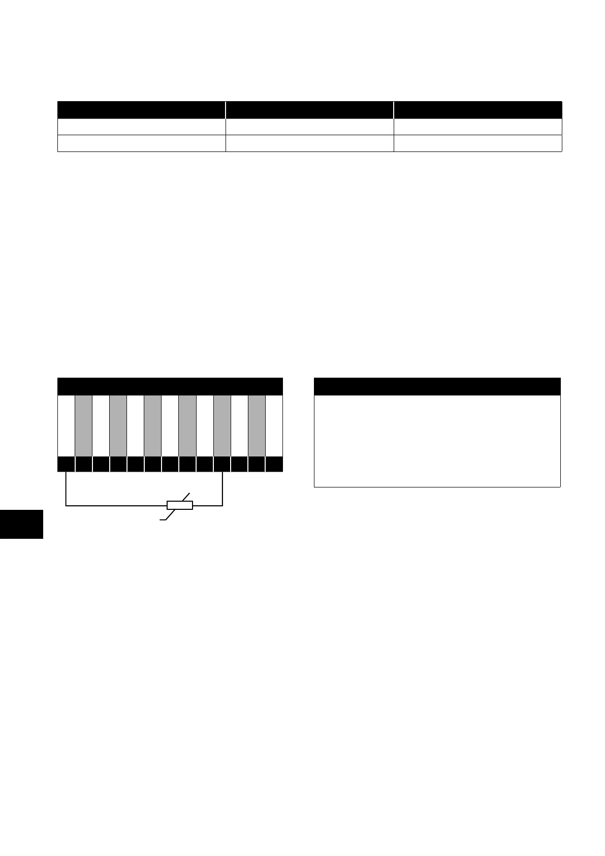
4.8.2. Motor Thermistor Connection
Where a motor thermistor is to be used, it should be connected as follows:
Motor Thermistor Connection Additional Information
+24V DC
DI 1
DI 2
DI 3
+10V DC
AI 1
0V / COM
AO 1
0V / COM
AI 2
AO 2
STO+
STO-
Compatible Thermistor: PTC Type, 2.5kΩ trip level.
Use a setting of P1-13 that has DI5/AI2 function as E-TRIP
“External Trip”, e.g. P1-13 = 6. Refer to section 7.2. Digital
Input Configuration Parameter P1-13 on page 38 for
further details.
Enable the Motor PTC Thermistor Input function in parameter
P2-33.
1
2
3
4
5
6
7
8
9
10
11
12
13
4
Electrical Installation