8 | HPI Combi Flow User Guide | Version 3.11 www.lafer t.com
3. Mechanical Installation
3.1. General
The HP Combi Flow should be mounted in a vertical position only, on a flat, flame resistant, vibration free mounting using the
integral mounting holes.
Do not mount flammable material close to the HP Combi Flow.
Ensure that the minimum cooling air gaps, as detailed in sections 3.7. Guidelines for Mounting (IP66 Units) on page 12 and
3.6. Guidelines for Mounting (IP55 Units) on page 11 are left clear.
Ensure that the ambient temperature range does not exceed the permissible limits for the HP Combi Flow given in section
11.1. Environmental.
Provide suitable clean, moisture and contaminant free cooling air sufficient to fulfil the cooling requirements of the HP Combi Flow.
3.2. Before Installation
Carefully unpack the HP Combi Flow and check for any signs of damage. Notify the shipper immediately if any exist.
Check the drive rating label to ensure it is of the correct type and power requirements for the application.
To prevent accidental damage always store the HP Combi Flow in its original box until required. Storage should be clean and dry
and within the temperature range –40°C to +60°C.
3.3. UL Compliant Installation
Note the following for UL-compliant installation:
For an up to date list of UL compliant products, please refer to UL listing NMMS.E334189.
The drive can be operated within an ambient temperature range as stated in section 11.1. Environmental on page 65.
UL Listed ring terminals / lugs must be used for all bus bar and grounding connections.
Refer to section 11.6. Additional Information for UL Compliance on page 68.
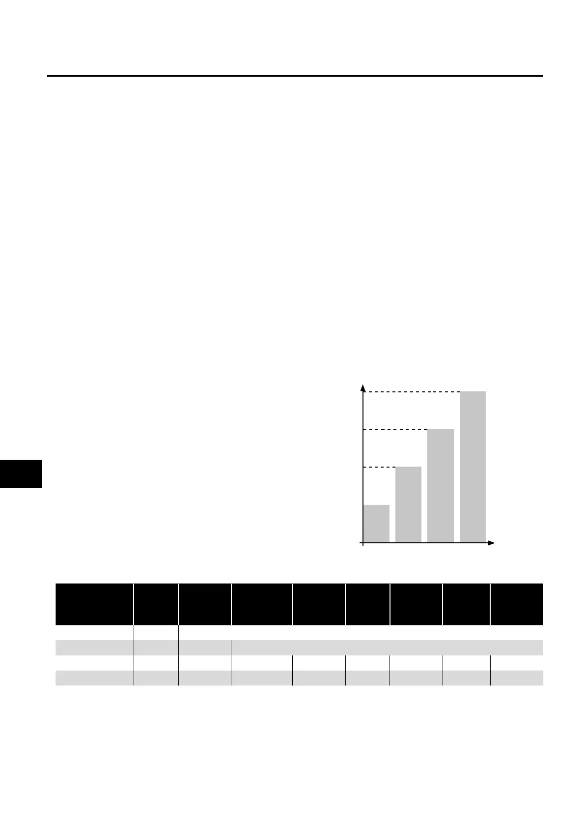
3.4. Installation Following a Period of Storage
Where the drive has been stored for some time prior to installation,
or has remained without the main power supply present for an
extended period of time, it is necessary to reform the DC capacitors
within the drive according to the following table before operation.
For drives which have not been connected to the main power supply
for a period of more than 2 years, this requires a reduced mains
voltage mains voltage to be applied for a time period, and gradually
increased prior to operating the drive. The voltage levels relative to
the drive rated voltage, and the time periods for which they must be
applied are shown in the following table. Following completion of the
procedure, the drive may be operated as normal.
NOTE This is only valid for non low harmonic version - see section
2.4.3. Low Harmonic Variants on page 7.
100%
75%
50%
25%
T1 T2 T3 T4
Storage Period
/Power-OFF
Period
Initial
Input
Voltage
Level
Time
Period T1
Secondary
Input
Voltage
Level
Time
Period T2
Third
Input
Voltage
Level
Time
Period T3
Final
Input
Voltage
Level
Time
Period T4
Up to 1 Year 100% N/A
1 – 2 Years 100% 1 Hour N/A
2 – 3 Years 25% 30 Minutes 50% 30 Minutes 75% 30 Minutes 100% 30 Minutes
More than 3 Years 25% 2 Hours 50% 2 Hours 75% 2 Hours 100% 2 Hours
3
Mechanical Installation