40 | HPI Combi Flow User Guide | Version 3.11 www.lafert.com
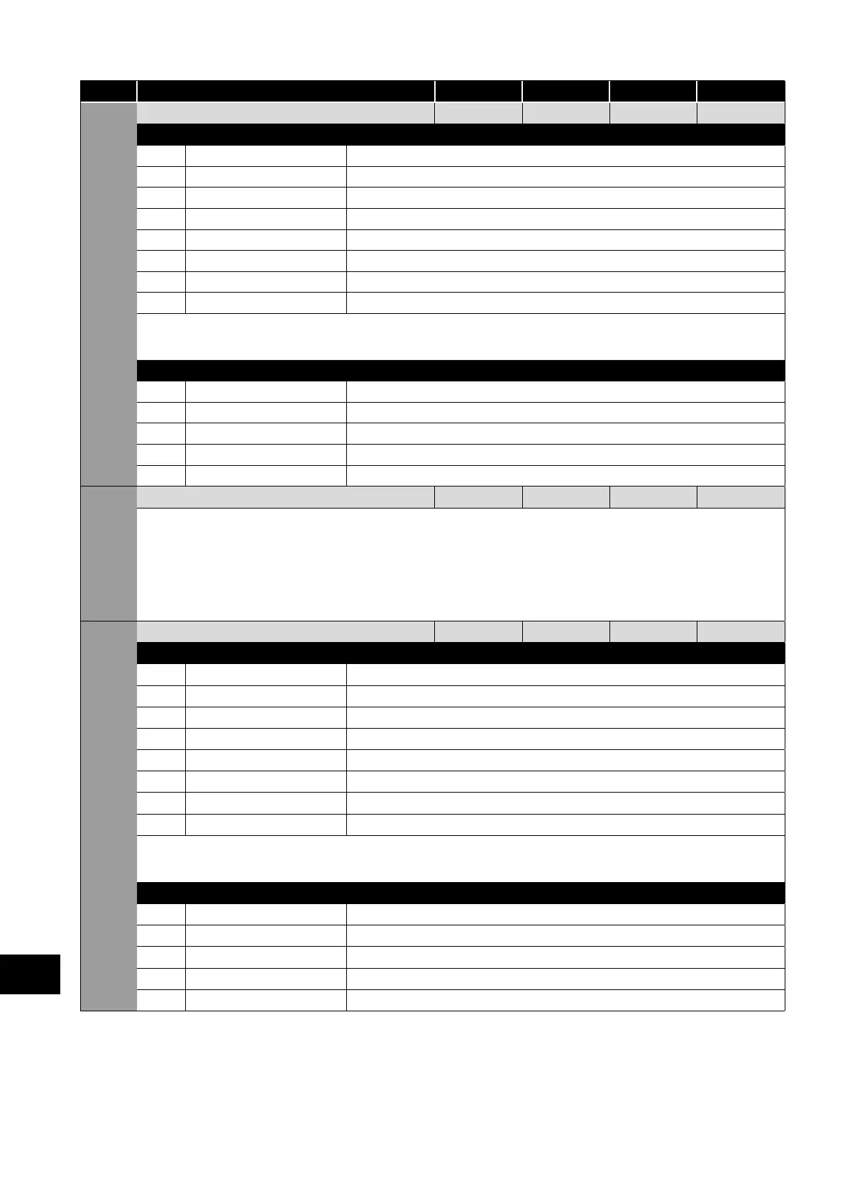
Par. Parameter Name Minimum Maximum Default Units
P2-11 Analog Output 1 Function 0 12 8 -
Digital Output Mode. Logic 1 = +24V DC
0 Drive running Logic 1 when the HP Combi Flow is enabled (Running).
1 Drive healthy Logic 1 When no Fault condition exists on the drive.
2 At speed Logic 1 when the output frequency matches the setpoint frequency.
3 Motor speed > 0 Logic 1 when the motor runs above zero speed.
4
Motor speed >= limit
Logic 1 when the motor speed exceeds the adjustable limit.
5 Motor current >=limit Logic 1 when the motor current exceeds the adjustable limit.
6 Motor torque >= Limit Logic when the motor torque exceeds the adjustable limit.
7 Analog input 2 >=limit Logic when the signal applied to the Analog Input 2 exceeds the adjustable limit.
NOTE When using settings 4 – 7, parameters P2-16 and P2-17 must be used together to control the behaviour. The output will switch
to Logic 1 when the selected signal exceeds the value programmed in P2-16, and return to Logic 0 when the signal falls below the
value programmed in P2-17.
Analog Output Mode
8 Motor speed 0 to P1-01.
9 Motor current 0 to 200% of P1-08.
10
Motor torque
0 to 200% of motor rated torque.
11 Motor power 0 to 150% of drive rated power.
12 PID Output Output from the internal PID Controller, 0 – 100%.
P2-12 Analog Output 1 Format - -
-
-
- = 0 to10V
- = 10 to 0V
- = 0 to 20mA
- = 20 to 0mA
- = 4 to 20mA
- = 20 to 4mA
P2-13
Analog Output 2 Function 0 12 9 -
Digital Output Mode. Logic 1 = +24V DC
0 Drive running Logic 1 when the HP Combi Flow is enabled (Running).
1 Drive healthy Logic 1 When no Fault condition exists on the drive.
2 At speed Logic 1 when the output frequency matches the setpoint frequency.
3 Motor speed > 0 Logic 1 when the motor runs above zero speed.
4
Motor speed >= limit
Logic 1 when the motor speed exceeds the adjustable limit.
5 Motor current >= limit Logic 1 when the motor current exceeds the adjustable limit.
6 Motor torque >= limit Logic when the motor torque exceeds the adjustable limit.
7 Analog input 2 >= limit Logic when the signal applied to the Analog Input 2 exceeds the adjustable limit.
NOTE When using settings 4 – 7, parameters P2-19 and P2-20 must be used together to control the behaviour. The output will switch
to Logic 1 when the selected signal exceeds the value programmed in P2-19, and return to Logic 0 when the signal falls below the
value programmed in P2-20.
Analog Output Mode
8 Motor speed 0 to P1-01.
9 Motor current 0 to 200% of P1-08.
10
Motor torque
0 to 200% of motor rated torque.
11 Motor power 0 to 150% of drive rated power.
12 PID output Output from the internal PID Controller, 0 – 100%.
9
Extended Parameters