EasyManua.ls Logo

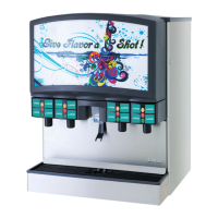
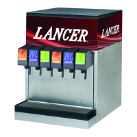
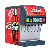
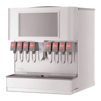
lancer 4400 Series - User Manual

lancer 4400 Series
48 pages
Print Icon
To Next Page IconTo Next Page
Loading...



“Lancer” is the registered trademark of Lancer © 2011 by Lancer, all rights reserved.

6655 Lancer Blvd.
San Antonio, Texas 78219
To order parts, call
Customer Service: 800-729-1500
Warranty/Technical Support: 800-729-1550
Email: custserv@lancercorp.com
www.lancercorp.com
Manual PN: 28-0255/11
OCT 2011
)"* ,$('+ '- %
 - %$,..+,"&"*,$#$"!


Table of Contents

Questions and Answers

  • A
    angelapruittSep 10, 2025
    What to do if the valve on my lancer 4400 will not shut off?
    • T
      Thomas PonceSep 10, 2025
      If your Lancer Dispenser valve will not shut off, try activating the valve a few times to free any debris. Then, remove the solenoid coil and plunger and clean out any foreign material. If the issue persists, the solenoid plunger may be sticking, and you should replace the solenoid coil.
  • M
    Misty BradfordSep 9, 2025
    Why is the carbonator pump in my lancer 4400 Dispenser noisy or cavitating?
    • T
      Tina CookSep 9, 2025
      If there is a noisy or cavitating carbonator pump in your Lancer Dispenser, verify that the incoming supply water pressure to the carbonator pump is a minimum of 25 PSI and a maximum of 50 PSI.
  • C
    carlanovakSep 8, 2025
    Why does the BIB pump fail to stop when I close the dispensing valve on my lancer 4400?
    • S
      Samuel MeltonSep 8, 2025
      If the BIB pump fails to stop when the dispensing valve is closed on your Lancer Dispenser, inspect the discharge line and fittings for leaks and repair or replace them as needed. Check if the BIB is empty and replace it if necessary. Also, look for air leaks on the inlet line or bag connector and repair or replace them.
  • R
    Rebecca MacdonaldAug 22, 2025
    Why is there insufficient soda flow in my lancer 4400 Dispenser (carbonated drinks)?
    • S
      saraguzmanAug 23, 2025
      If your Lancer Dispenser has insufficient soda flow for carbonated drinks, first verify that the incoming CO2 pressure is between 70-75 PSI. Then, ensure the shutoff on the mounting block is fully open. If the problem persists, the soda flow control may have foreign debris; remove it from the valve and clean it. Finally, a defective LFCV module could be the cause, and you may need to replace it.
  • T
    Thomas SheppardSep 5, 2025
    Why does the BIB pump continue to operate when the bag is empty on my lancer 4400?
    • R
      Ryan LaraSep 6, 2025
      If the BIB pump continues to operate when the bag is empty in your Lancer Dispenser, check for a leak in the suction line and replace the line if necessary. Also, inspect the o-ring on the pump inlet fitting for leaks and replace the o-ring if needed. If neither of these resolves the issue, the syrup BIB pump may be defective and require replacement.
  • L
    Lauren GrahamSep 4, 2025
    Why is the BIB pump operating, but there's no flow in my Lancer Dispenser?
    • W
      William BoydSep 4, 2025
      If the BIB pump is operating but there is no flow in your Lancer Dispenser, check for a leak in the syrup inlet or outlet line and replace the line if necessary. If there are no leaks, the BIB pump may be defective and need replacement.
  • A
    amanda68Sep 3, 2025
    Why doesn't the BIB pump operate when I open the dispensing valve on my Lancer Dispenser?
    • J
      jenkinsstephanieSep 3, 2025
      If the BIB pump in your Lancer Dispenser does not operate when the dispensing valve is opened, check if you are out of CO2, if the CO2 is not turned on, or if the CO2 pressure is low; replace the CO2 supply, turn on the CO2 supply, or adjust the CO2 pressure to 70-80 PSI. Also, check if you are out of syrup and replace the syrup supply if necessary. Ensure the BIB connector is fastened tightly and straighten or replace any kinked syrup or gas lines.
  • T
    Thomas LoganSep 2, 2025
    Why is the circuit breaker tripping on my Lancer Dispenser?
    • K
      Kaitlyn AndersonSep 2, 2025
      If the circuit breaker is tripping on your Lancer Dispenser, detect a short by disconnecting valve harnesses from the switch panel (4 25-pin harnesses and 4 9-pin harnesses), then restore power. If the breaker doesn't trip, find and replace the shorted harness. If it still trips, reinstall the 8 harnesses and disconnect the white 5-pin harness from the controller PCB, then restore power again. If the breaker doesn't trip, replace the controller PCB. If it continues to trip, reinstall the white 5-pin harness and locate the short from a motor or solenoid harness and replace it. If the breaker still trips, disconnect all harnesses connected to the power supply and restore power. If it continues to trip, replace the power supply.
  • R
    Ryan WilsonSep 1, 2025
    Why is water continually leaking at the connections of my lancer 4400 Dispenser?
    • T
      thomasloriSep 1, 2025
      If you have water continually leaking at the connections of your Lancer Dispenser, tighten the water connections. If the flare seal washer is leaking, replace it.
  • A
    April AndersonAug 30, 2025
    What to do if my lancer 4400 Dispenser dispenses only water or only syrup?
    • L
      Laura JohnsonAug 31, 2025
      If your Lancer Dispenser only dispenses water or only dispenses syrup, first replace the syrup BIB if it's empty. Ensure the water or syrup shutoff on the mounting block is fully open. Check for proper water and syrup supply by removing the valve from the mounting block and opening the shutoffs slightly. If there's no supply, check the dispenser for other problems and ensure the BIB connection is engaged. Verify the CO2 pressure to the pump is between 70-80 PSI. If the BIB pump is stalled or inoperative, check the CO2 pressure and/or replace the pump. Remove any kinks in the line, and if necessary, repair or replace the CO2 regulator. Finally, a defective LFCV module may need replacement.

Summary

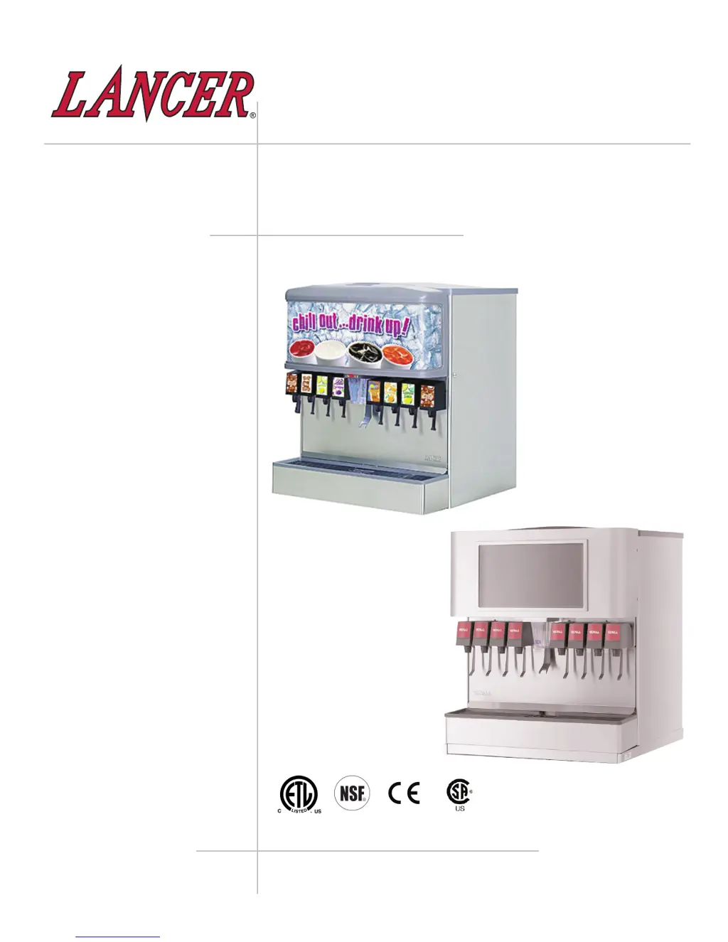
ABOUT THE LANCER IBD 4500;4600;LCD Series

PRE-INSTALLATION CHECKLIST

Checklist for preparing the dispenser before installation.

SPECIFICATIONS - 22 MODELS

ICE BEVERAGE DISPENSER 22

Technical specifications for the 22-inch IBD models.

DIMENSIONS & WEIGHT

Physical measurements and weight of the 22-inch dispenser.

SPACE REQUIRED & FITTINGS

Installation clearances and connection specifications for the 22-inch unit.

WATER SUPPLY REQUIREMENTS

Plain and soda water supply pressure and flow requirements.

SPECIFICATIONS - 30 MODELS

ICE BEVERAGE DISPENSER 30

Technical specifications for the 30-inch IBD models.

DIMENSIONS & WEIGHT

Physical measurements and weight of the 30-inch dispenser.

SPACE REQUIRED & FITTINGS

Installation clearances and connection specifications for the 30-inch unit.

WATER SUPPLY REQUIREMENTS

Plain and soda water supply pressure and flow requirements.

SAFETY WARNINGS

GENERAL SAFETY PRECAUTIONS

Important safety precautions and operating limitations for the dispenser.

ELECTRICAL SAFETY PRECAUTIONS

Essential safety measures for electrical connections and maintenance.

HAZARDOUS MATERIALS AND WATER SUPPLY

CARBON DIOXIDE HANDLING AND RISKS

Information on CO2 properties, risks, and leak prevention.

WATER SUPPLY REQUIREMENTS

Guidelines for potable water supply, pressure, and backflow prevention.

INSTALLATION HIGHLIGHTS

CRITICAL INSTALLATION STEPS

Ten essential steps for a successful dispenser installation.

AUTOMATIC AGITATION AND ALARMS

AUTOMATIC AGITATION CONTROL

Information on automatic agitation and low ice alarm operation.

INSTALLATION PROCEDURE

UNPACKING AND INITIAL SETUP

Steps for safely unpacking and initial setup of the dispenser.

DRAIN SPIDER INSTALLATION

Proper positioning and reinstallation of the drain spider.

LOCATION SELECTION

CHOOSING AN INSTALLATION LOCATION

Guidelines for choosing a suitable installation location.

DISPENSER INSTALLATION DETAILS

ICEMAKER INSTALLATION CONSIDERATIONS

Points to consider when installing an icemaker with the dispenser.

LEVELING THE DISPENSER

Procedures for ensuring the dispenser is level for optimal performance.

WATER SUPPLY CONNECTION

Instructions for connecting plain and soda water supply lines.

CONNECTING UNIT COMPONENTS

CARBONATOR CONNECTION

Steps for connecting the carbonator motor and pump.

ELECTRICAL CONNECTION AND GROUNDING

Guidelines for safe electrical connection and proper grounding.

UNIT INSTALLATION AND ICEMAKER WARNING

INSTALLATION OF THE UNIT

Detailed steps for assembling and installing the dispenser unit.

ICEMAKER INSTALLATION WARNING

Caution regarding ice level and icemaker clearance during installation.

VALVE AND LCD INSTALLATION

LCD MONITOR INSTALLATION

Steps for installing the LCD monitor and connecting it.

ICE FLOW REGULATOR ADJUSTMENT

How to adjust the ice flow regulator for optional kits.

VALVE INSTALLATION MODELS

Details on installing and adjusting Models 100, 145, and 150 valves.

CLEANING AND SANITIZING INSTRUCTIONS

GENERAL CLEANING AND SANITIZING GUIDELINES

General guidelines for cleaning and sanitizing Lancer equipment.

CLEANING SOLUTION PREPARATION

How to mix and use the recommended cleaning solution.

SANITIZING SOLUTION PREPARATION

How to prepare and use the recommended sanitizing solution.

DAILY CLEANING AND MAINTENANCE

POST-SANITIZATION RINSING CAUTION

Cautionary note on rinsing after sanitizing for health safety.

DAILY CLEANING PROCEDURES

Steps for daily cleaning of dispenser surfaces and parts.

LCD MONITOR AND MERCHANDISER LENS CLEANING

Instructions for cleaning the LCD screen and merchandiser lens.

ICE BIN CLEANING WARNING

Warning regarding automatic agitation and power disconnection for ice bin cleaning.

SPECIFIC CLEANING PROCEDURES

ICE BIN CLEANING PROCEDURES

Detailed steps for cleaning the ice bin and its components.

BEVERAGE COMPONENT CLEANING (BAG-IN-BOX)

Instructions for cleaning beverage lines and components for BIB systems.

COMPONENT CLEANING AND SERVICING

ICE CHUTE CLEANING PROCEDURE

Steps for cleaning the ice chute monthly or more often.

MONITOR REMOVAL FOR SERVICING

Instructions on how to remove the monitor for service.

MONITOR SERVICING AND WARRANTY

MONITOR SERVICE AND REINSTALLATION

Completing service and reversing the monitor removal process.

MONITOR WARRANTY COVERAGE

Details on warranty claims, exclusions, and processing.

TROUBLESHOOTING

TROUBLESHOOTING COMMON ISSUES

Detailed guide to diagnosing and resolving common dispenser problems.

LIGHT EMITTING DIODES (LEDS)

LED INDICATOR DESCRIPTIONS

Explains the function of various LEDs on the PC board for diagnostics.

SPECIFIC LED FUNCTIONS

Details on LEDs D3 through D6 and their operational states.

AUTOMATIC AGITATION AND ALARMS

LED INDICATOR FUNCTIONS (CONTINUED)

Explains the function of LEDs D7 through D9.

DIP SWITCH CONTROLS FOR AGITATION

Explains DIP switches for controlling agitation timing and alarms.

ILLUSTRATIONS AND PARTS LISTINGS

DECALS AND LABELS DIAGRAM

Diagram showing the location of decals and labels on the dispenser.

DECALS AND LABELS

PARTS LIST FOR DECALS AND LABELS

Detailed list of part numbers for various decals and labels.

FINAL ASSEMBLY - POST-MIX IBD AND ICE DISPENSER

FINAL ASSEMBLY EXPLODED VIEW

Diagram illustrating the final assembly of post-mix IBD and ice dispenser.

FINAL ASSEMBLY PARTS LIST

PARTS FOR FINAL ASSEMBLY

Detailed list of parts for the final assembly of the dispenser.

LCD UNIT ASSEMBLY

LCD UNIT EXPLODED VIEW

Diagram showing the assembly of the LCD unit.

LCD UNIT PARTS LIST

PARTS FOR LCD UNIT ASSEMBLY

Detailed list of parts for the LCD unit assembly.

NO COLD PLATE UNIT ASSEMBLY

NO COLD PLATE UNIT EXPLODED VIEW

Diagram showing the assembly of the unit without a cold plate.

NO COLD PLATE UNIT PARTS LIST

PARTS FOR NO COLD PLATE UNIT

Detailed list of parts for the no cold plate unit assembly.

FAUCET PLATE AND ICE CHUTE ASSEMBLY

FAUCET PLATE AND ICE CHUTE EXPLODED VIEW

Diagram showing the faucet plate and ice chute sub-assembly.

FAUCET PLATE AND ICE CHUTE PARTS LIST

PARTS FOR FAUCET PLATE AND ICE CHUTE

Detailed list of parts for the faucet plate and ice chute sub-assembly.

ELECTRICAL BOX AND GEAR MOTOR ASSEMBLY

ELECTRICAL BOX AND GEAR MOTOR EXPLODED VIEW

Diagram of the electrical box and gear motor sub-assembly.

ELECTRICAL BOX AND GEAR MOTOR PARTS LIST

PARTS FOR ELECTRICAL BOX AND GEAR MOTOR

Detailed list of parts for the electrical box and gear motor sub-assembly.

PELLET ICE DISPENSER SUB-ASSEMBLY

PELLET ICE DISPENSER DIAGRAM

Diagram of the pellet ice dispenser sub-assembly and conversion kit.

PELLET ICE DISPENSER PARTS LIST

List of parts for the pellet ice dispenser sub-assembly.

WIRING DIAGRAM - 115 V;60 HZ

115 VAC WIRING DIAGRAM

Wiring diagram for the 115V/60Hz dispenser models.

WIRING DIAGRAM - 230 V;50-60 HZ

230 VAC WIRING DIAGRAM

Wiring diagram for the 230V/50-60Hz dispenser models.

AGITATION CONTROLS - EXPANDED VIEW

EXPANDED VIEW OF AGITATION CONTROLS

Detailed explanation of agitation control settings and DIP switches.

RECOMMENDED PLUMBING

SIX (6) VALVE PLUMBING DIAGRAM

Recommended plumbing configuration for a six-valve dispenser.

EIGHT (8) VALVE PLUMBING DIAGRAM

Recommended plumbing configuration for an eight-valve dispenser.

COUNTER CUTOUT - IBD 22

22 COUNTER CUTOUT DIMENSIONS

Technical drawings and dimensions for the 22" dispenser cutout.

COUNTER CUTOUT - IBD 30

30 COUNTER CUTOUT DIMENSIONS

Technical drawings and dimensions for the 30" dispenser cutout.

DISPENSER DISPOSAL

PROPER DISPOSAL PROCEDURES

Guidelines for environmentally safe disposal of the dispenser unit.

lancer 4400 Series Specifications

General IconGeneral
Series4400 Series
Valve MaterialStainless Steel
Number of Flavors4
Number of Flavor Valves4
Product CompatibilityCarbonated Beverages
Warranty1 Year Limited
Model NameLancer 4400 Series

Related product manuals