6
Read This Manual
This manual was developed by Lancer Corporation as a reference guide for the owner/operator and installer
of this dispenser. Read this manual before installation and operation of this dispenser. See pages 16-21 for
troubleshooting or service assistance. If the service cannot be corrected please call your Service Agent or
Lancer Customer Service. Always have your model and serial number available when you call.
INSTALLATION
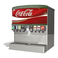
Unpacking the Dispenser
Inspection of Drain Spider
1. Set shipping carton upright on the oor then cut package
banding straps and remove.
2. Open top of carton and remove interior packaging.
3. Lift carton up and o of the unit.
4. Remove plywood shipping base from unit by moving unit so
that one side is o the counter top or table allowing access
to screws on the bottom of the plywood shipping base.
Lancer does NOT recommend the use of shaved or
akeiceinthedispenser.
NOTE
5. Remove accessory kit and loose parts from ice
compartment.
If unit is to be transported, it is advisable to leave the
unit secured to the plywood shipping base.
NOTE
The drain spider is located to the right side near the front of the bin under the ice shroud. The coldplate has a cavity
designed to hold the drain spider. During shipment, the drain spider may become dislodged from its original position.
Prior to installing the unit, ensure the drain spider is in the correct position.This will prevent drain clog issues. Inspect
the lower bin area and reach under the shroud to ensure the drain spider is secure in the coldplate cutout. If the spider
is not in place, proceed with the following steps.
NOTE
Inspect unit for concealed damage. If evident, notify
deliveringcarrierandleaclaimagainstthesame.
NOTE
6. If leg kit has been provided, assemble legs by tilting unit.
DO NOT LAY UNIT ON ITS SIDE OR BACK
! ATTENTION
1. Remove agitator clip and pin from agitator bar.
2. Remove agitator bar from the hub.
3. Remove ice shroud by lifting the side opposite the auger and rotating out from beneath the auger.
4. Locate drain spider and reinstall in the coldplate cavity where drain line exits.
5. Reinstall all components. Ensure agitator clip is locked.
Selecting/Preparing a Counter Location
1. Select a level, well ventilated location that is in close
proximity to a properly grounded electrical outlet, within ve
(5) feet (1.5 m) of a drain, a water supply that meets the
requirements shown in the Specications section found on
page 4, away from direct sunlight or overhead lighting, and
has sucient clearance for air circulation.
2. Sucient clearance must be provided (if an ice maker is
not installed) to allow lling ice compartment from a ve (5)
gallon bucket (a minimum of 16 inches is recommended).
- Drain Spider
Inspect the counter location where the unit is to be
installed. Verify the selected counter is strong enough
to safely support the weight of the dispenser, the ice,
andtheicemaker(ifnecessary)aftercountercutout
ismade.Thetotalweight(withicemaker)forthisunit
couldexceed800pounds(383.6kg).
! ATTENTION
The dispenser should only be installed in a location
where it can be overseen by trained personnel
NOTE