Section 1: Assembly & Set-Up
Table of Contents
RCF3096, RCF3010, & RCFM3010 Rotary Cutters 326-566M11/8/18
31
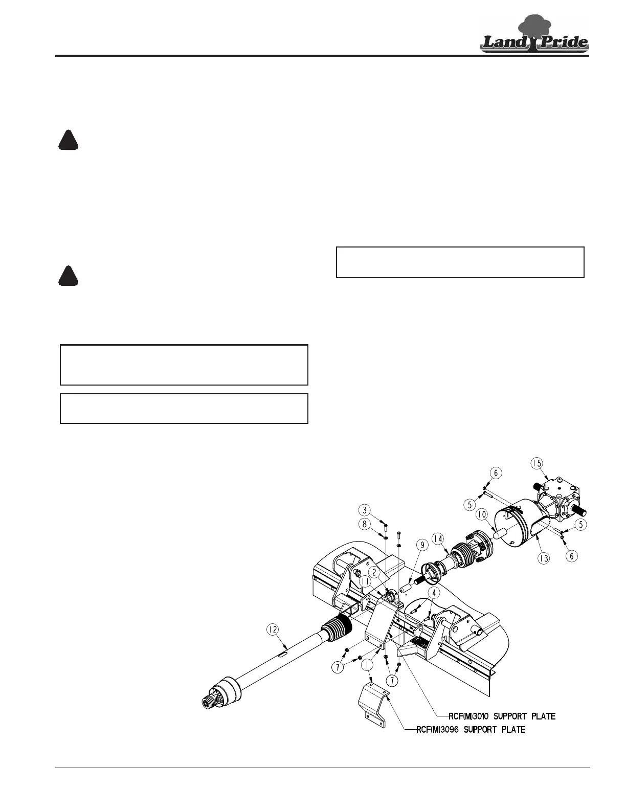
Constant Velocity Hitch Assembly (RCF3010 Shown)
Figure 1-26
35214
Constant Velocity Driveline (Pull-Type)
The following instructions are for installation of a
“Constant Velocity Driveline”. Instructions for “Equal
Angle Driveline” begin on page 30.
DANGER
!
To avoid serious injury or death:
• Make certain driveline yokes are securely fastened at each
end. A loose yoke can work free allowing the driveline to
rotate uncontrollably causing implement damage and
bodily injury or death to anyone nearby.
• Do not use a power take-off adapter. The adapter will
increase strain on the tractor’s power take-off shaft causing
possible damage to shaft and driveline. It will also defeat
the purpose of the tractor’s power take-off shield.
WARNING
!
To avoid serious injury or death:
Maximum constant velocity driveline turning angle is limited
to 80 degrees Exceeding this angle can cause the driveline to
break and send flying objects.
Refer to Figure 1-26:
1. Remove pillow block bearing (#11) from bearing
support (#1). Keep hardware for reattachment.
2. Attach bearing support (#1) to the front guards with 1/
2"-13 x 1 1/2" bolts (#4) and whiz nuts (#7). Tighten
hex whiz nuts to the proper torque.
3. Remove shaft protector (#10) from input shaft of
gearbox (#15).
4. Pry open access doors (#13) in the gearbox shield by
placing a tool in the notch at the back of both doors.
IMPORTANT: The drivelines must be lubricated
before putting them into service. Refer to
“Lubrication Points” on page 61.
NOTE: Bearing support is to be placed in front of
chain/rubber guarding.
5. Remove conical dog pin or bolts (#5) and fastening
hardware (#6) from slip-clutch end of driveline (#14).
6. Slide slip-clutch end of driveline (#14) onto gearbox
input shaft.
7. Attach slip-clutch end of driveline to gearbox input
shaft with existing conical dog pin or bolts (#5)
and removed hardware (#6). Tighten conical
dog pin or bolts (#5) to 45-50 ft-lb torque.
8. Push/pull on driveline yoke to be sure it is securely
fastened to the gearbox shaft.
9. Rotate access doors (#13) closed and snap in place.
10. Remove rubber protective sleeve (#9) from end of
jackshaft driveline (#14).
11. Fully insert jackshaft driveline (#14) into pillow block
bearing (#11).
12. With locking collar (#2) facing forward, attach pillow
block bearing (#11) to bearing support (#1) with
1/2"-13 x 1 3/4" cap screws (#3), flat washers (#8),
and hex whiz nuts (#7). Tighten nuts to the correct
torque.
13. Rotate locking collar clockwise until tight and then
tighten set screw in locking collar (#2).
14. Attached bolted coupler end of main driveline (#12)
to jackshaft driveline (#14). Push main driveline onto
the jackshaft driveline as far as possible and then
tighten bolted connection.
NOTE: Make sure bearing locking collar (#2) is
facing forward toward the tractor.




 To Next Page