2-
1
2: Installation
This chapter covers the installation of the MSS in an Ethernet network and the attachment
of a serial device. Basic knowledge of networking installation is assumed. Read this chapter
completely before continuing.
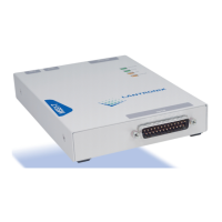
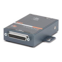
2.1 Components
The MSS front panel has a male DB25 serial connector. The following figure shows an
MSS front panel.
Figure 2-1:
MSS Front Panel
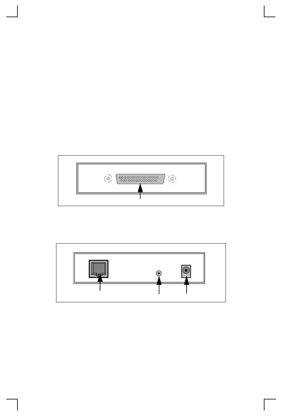
The MSS rear panel has an RJ45 Ethernet connector, a reset button, and a power connector.
The following figure shows an MSS rear panel.
Figure 2-2:
MSS Rear Panel
Note:
When the reset button is pressed and held during the power up and
boot procedures, the MSS returns to its factory default configuration.
Serial
DB25 Serial Port
10/100 BaseT
regulated 5V DC
Reset
Power ConnectorReset ButtonRJ45 Ethernet Port

 Loading...