EasyManuals Logo

Lantronix MSS100 Installation Guide

Lantronix MSS100
71 pages
To Next Page IconTo Next Page
To Previous Page IconTo Previous Page
Page #58 background imageLoading...
Page #58 background image
C-1
C: Pinouts
In the following diagrams, unlabeled pins are not connected.
C.1 Ethernet Connector
The MSS uses a standard Ethernet pinout. The figure below shows the MSS RJ45
Ethernet connector pin connections.
Figure C-1: RJ45 Ethernet Connector
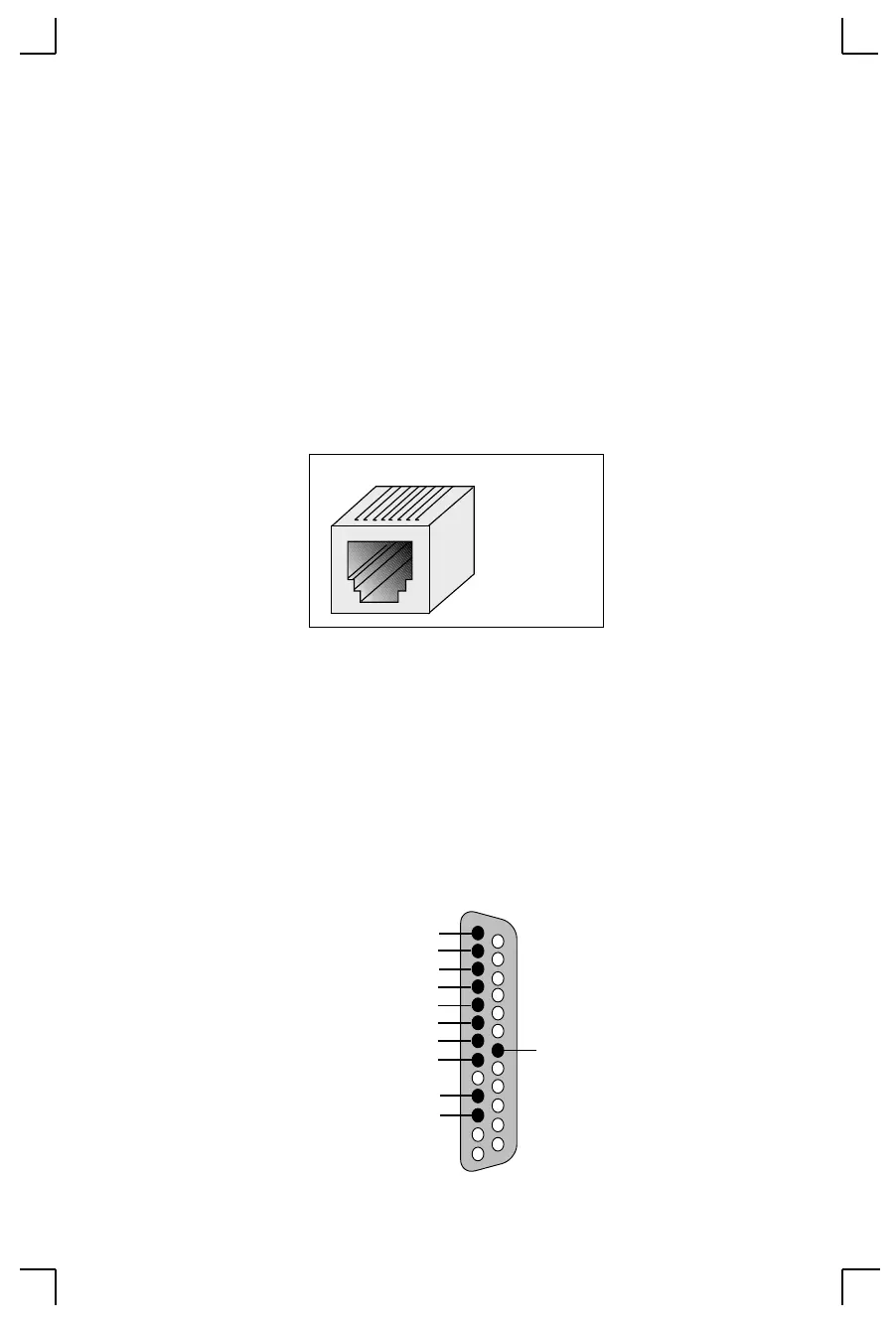
C.2 MSS Serial Connector
C.2.1 DB25 Connector
The figure below shows the pin connections of the MSS DB25 connector.
Figure C-2: DB25 Serial Connector
1 2 3 4 5 6 7 8
1 RX+
2 RX-
3 TX+
6 TX-
TX (out)
RX (in)
RTS (out)
CTS (in)
DSR (in)
DTR (out
1
14
GND
CD (in)
Shield
PWR GND*
+5V*
DTE DB25 Male
1
3
25

Table of Contents

Other manuals for Lantronix MSS100

Questions and Answers:

Question and Answer IconNeed help?

Do you have a question about the Lantronix MSS100 and is the answer not in the manual?

Lantronix MSS100 Specifications

General IconGeneral
BrandLantronix
ModelMSS100
CategoryServer
LanguageEnglish

Related product manuals