Description and Specifications
XPort™ Integration Guide 11
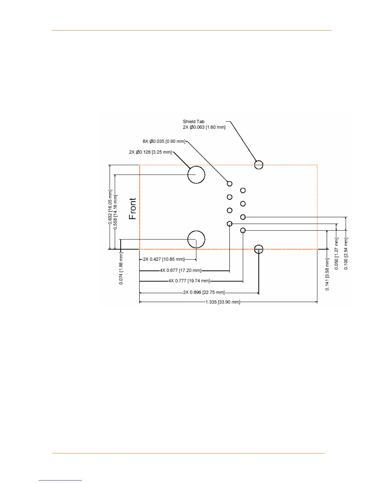
Recommended PCB Layout
The hole pattern and mounting dimensions for the XPort device server are shown in
the following drawing. For proper heat dissipation, it is recommended that the PCB
have approximately 1 square inch of copper attached to the shield tabs. The shield
tabs are an important source of heat sinking for the device.
Figure 2-7. PCB Layout
Product Information Label
The product information label contains important information about your specific unit,
such as its product ID (name), bar code, part number, and Ethernet (MAC) address.

 Loading...