Description and Specifications
XPort™ Integration Guide 9
Ethernet Interface
The Ethernet interface magnetics, RJ45 connector, and Ethernet status LEDs are all
in the device server shell.
Table 2-2. Ethernet Interface Signals (Industry Standards)
Signal Name DIR Contact Primary Function
TX+ Out 1 Differential Ethernet transmit data +
TX- Out 2 Differential Ethernet transmit data -
RX+ In 3 Differential Ethernet receive data +
RX- In 6 Differential Ethernet receive data -
Not used 4 Terminated
Not used 5 Terminated
Not used 7 Terminated
Not Used 8 Terminated
SHIELD Chassis ground
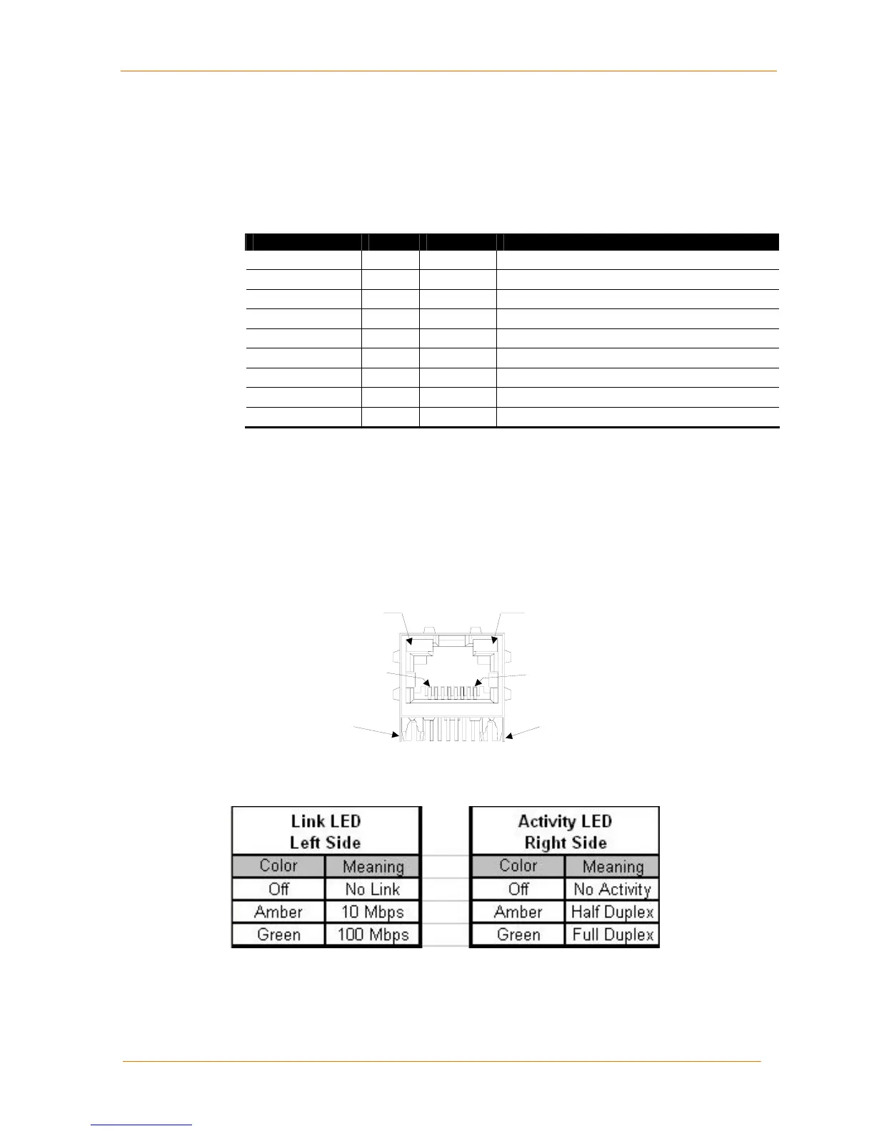
LEDs
The XPort contains the following LEDs:
Link (bi-color, left LED) ⎯ XPort-03 and greater only
Activity (bi-color, right LED)
Figure 2-3. XPort LEDs
CONTACT 1
CONTACT 8
LEFT
LED
RIGHT
LED
SHIELD TABSHIELD TAB
Table 2-3. XPort LED Functions (XPort-03 and greater only)

 Loading...