Development Kit
XPort™ Integration Guide 19
SW1-4, SW1-5 Options
SW1-5 controls the routing of the CP3/CTS/DCD signal from the XPort. CP3 is
connected to pin 8 of the XPort, and you can software configure it as RTS, LED3,
DTR, IN3, or OUT3. With SW1-5 in the OFF position, the CP3 signal is routed to
SW1-4. SW1-4 and SW1-5 are inputs to the PLD, which does the actual switching.
The drawings represent the logical switching functions.
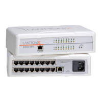
CP3 options are a little more complicated because both SW1-4 and SW1-5 are used
in the configuration setup. In this drawing, SW1-5 is OFF, which connects XPort pin-8
to the RS-232 transceiver. The XPort CP3 is configured for RTS. SW1-4 is ON,
routing the signal from XPort pin-8 to P1 pin-7 (RTS).
Figure 3-5. SW1-5 OFF and SW1-4 ON
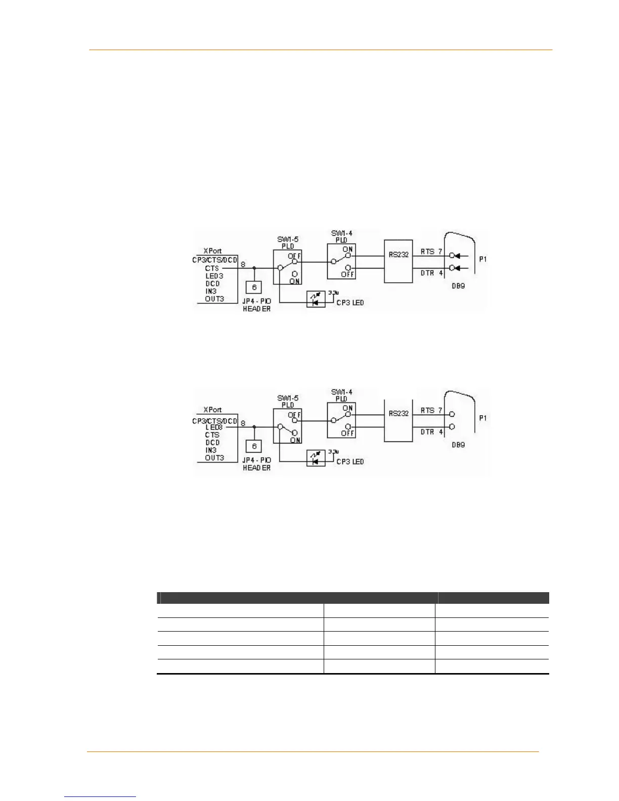
In the next drawing, SW1-5 is ON, which disconnects XPort pin-8 from the RS-232
transceiver. The XPortCP3 is configured for LED3.
Figure 3-6. SW1-5 ON and SW1-4 ON
When CP3 is configured for LED3, it functions as a diagnostic indicator. The LED3
signal in combination with the LED1 signal indicates diagnostic information as shown
in the following table.
Note: CP1 must be configured for LED1, and CP3 must be configured for
LED3 for diagnostic mode.
Table 3-4. LED States
Condition CP3 LED (LED3) CP1 LED (LED1)
No errors OFF ON
Network controller error ON Blink 3x/4 sec OFF
Duplicate IP address present ON Blink 5x/4 sec OFF
No DHCP response Blink 2x/sec Blink 5x/4 sec OFF
Setup menu active Blink 2x/sec See Note.

 Loading...