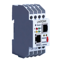
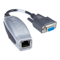
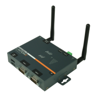
Development Kit
16 XPort™ Integration Guide
XPort Signal XPort Pin # Direction DB9 Pin # DTE Device Signal
Ground 1 -- 5 GND
CTS 8 In 7 RTS
RTS 6 Out 8 CTS
Note: The supplied CD contains a configurable pins control web applet that
lets you view the state of the configurable GPIO pins. This applet is provided
in the Sample Code and Solutions folder.
RS-232 Port
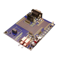
The evaluation board uses a TI SN75C3238 IC to convert all RS-232 interface
signals to 3.3V CMOS-level XPort signals.
We selected the interface IC for its capability of true RS-232-level performance from
a +3.3V power source and for its 15 kV ESD protection. The part also includes an
RS-232 valid output that lights an LED by means of the PLD circuit.
Power Supply
The evaluation board contains a +3.3V regulator that receives input power by means
of a 2.5mm input power jack. The input power should be 5VDC from a regulated DC
source. The evaluation kit provides a +5VDC power module.
We recommend that you also connect the evaluation board to an earth ground. You
can use the chassis ground rectangle (copper tape), TP7, or the shell of the DB9
connector.
General Control PLD
The purpose of the PLD is to provide general evaluation board mode control and
LED signal-level monitoring. The PLD works with the 6-position mode control switch
(SW1) and the timer and reset circuits to provide mode control.
The PLD is a Lattice ISPLSI2032VE part, which is contained in a 48-pin TQFP
package. This part contains 32 I/O and 32 microcells and is in-circuit programmable.
A 1x8-pin header (JP3) provides for standard Lattice in-circuit programming.
Configuration Switch Bank
Switch module SW1 contains six independent switches for configuring the PLD on
the evaluation board. The PLD controls how the signals from the XPort are routed on
the evaluation board. Positions 1 and 6 are for self-test. Positions 2 through 5 are for
configuring XPort pins for various operations.
Three XPort pins are configurable pins. You can configure these pins for hardware
flow control or as LED status indicators on the evaluation board. For information
about configuring these pins, see the XPort User Guide.
On the evaluation board, configurable pins are shown as CP1, CP2, CP3, and SW1
switch positions are shown as SW1-1 through SW1-6.
Note: In the following sections, the terms LED1 and LED3 refer to diagnostic
modes. You can put control of two of the XPort pins into these modes.
 Loading...
