LAUNCH X-431 GDS User’s Manual
2.1.2 Structure
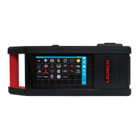
1. Structure view
Figure 2-2 X-431 GDS Main set structure view
Table 2-1: X-431 GDS terminals and indicators description
No. Name Descriptions
1 Handle Holding or carrying the main unit.
2 SIM slot Not applied for X-431 GDS.
3 Exhaust vent For expelling heating to ensure normal
temperature of internal parts.
4 VGA terminal Connect to projector or display.
5 LAN terminal Connect to wire network with LAN cable.
6 Diagnose terminal Connect to test cable.
7 USB ports Connect to USB devices. While
connecting function boxes, Scopebox
must be connected to the blue USB port.
8 Hard Disk indicator
(green)
Indicates diagnosis communication state.
9 Power indicator (red)
Indicates power status.
10 Power connector Connect to outer power to supply power or
charge for main unit.
4