LAUNCH X-431 GDS User’s Manual
Table 2-3: Sensorbox terminals and indicators description
No. Name Description
1 Data receiving
indicator
Indicator (green) for receiving data from main
unit.
2 Data sending
indicator
Indicator (green) for sending data to main unit.
3 Power indicator It keeps steady on (red) after Sensorbox is
powered on.
4 B type USB port Connect to main unit with USB cable when it is
applied as separated USB device.
5 Power connector
Connect to power supply through the power
adaptor.
6 COM Common terminal of multimeter
7 VΩHz Testing terminal of multimeter
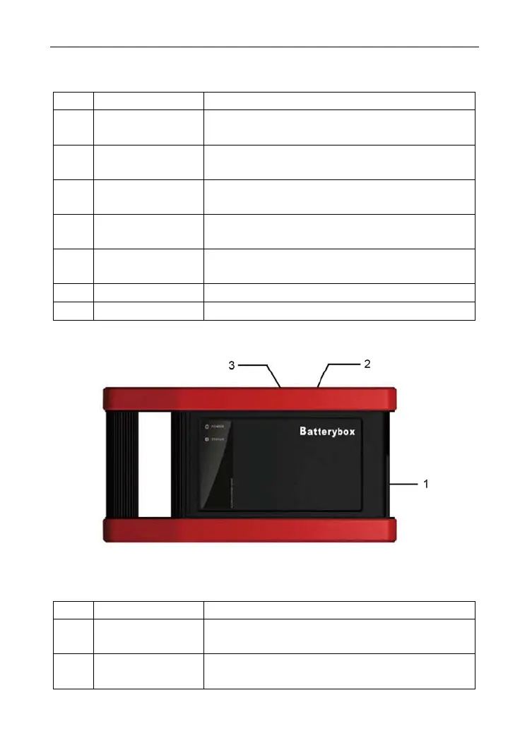
4. Batterybox structure
Figure 2-5 Batterybox structure view
Table 2-4: Batterybox terminals and indicators description
No. Name Description
1 Battery
connector
Connect to battery via cable for testing battery
2 Power connector
Connect to power supply via the power
adaptor. (unused)
7