LAUNCH X-431 GDS User’s Manual
3 Communication
indicator
Blinks green during data communication
4 Operation indicator
(green)
Keeps lighting after oscilloscope operated.
5 Power indicator
(red)
Keeps lighting after scopebox powered on.
6 1K calibration signal
terminals (2 pcs)
One terminal: 1K square wave signal
output, 2VP-PVP-P.
The other terminal: connect to the ground.
7 CH1 Channel 1
8 CH2 Channel 2
9 CH3 Channel 3
10 CH4 Channel 4
11 External trigger External trigger signal
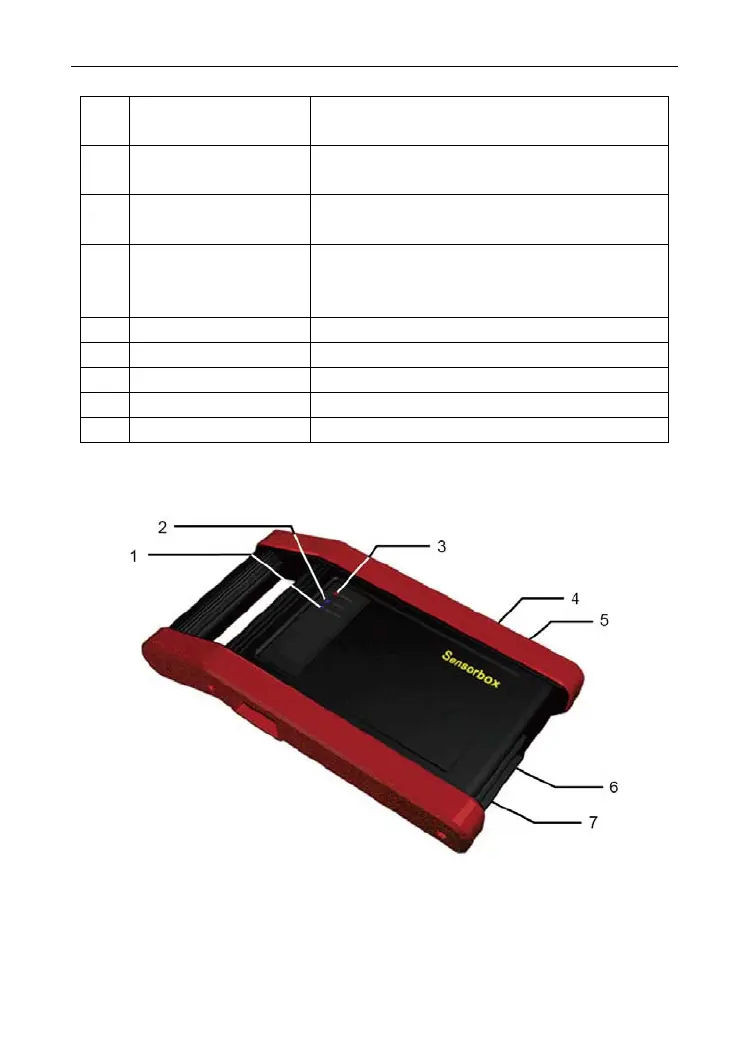
3. Sensorbox structure
Figure 2-4 Sensorbox structure view
6