Launch TLT245AT / TLT250AT(C) Two-post lift’s Installation manual
7
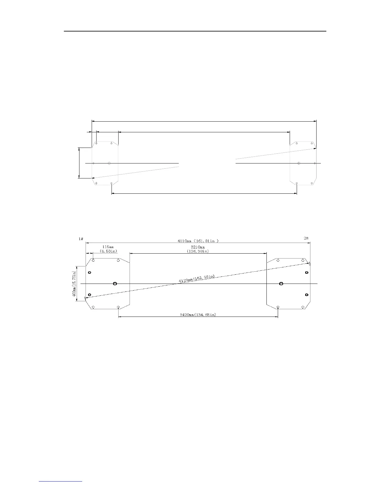
5.2.2 Base plate layout
TLT245AT base plate installation is shown in Fig5a,
TLT250AT(C)base plate installation is shown in Fig5b:
z With total width (A) as the basis, draw two parallel
lines (#1 and #2) on the concrete slab, with the error
within 3mm.
z Determine the power side column location on any
chalk line, and mark the total width (B) of the base
plate. Mark the points 3 and 4
z Starting from point 3, draw one diagonal line
(C) ,forming a triangle. In this way, the vertical lines
can determine the location of the two columns
4
3
C
A
2#1#
70mm(2.8in)
400mm(15.7in)
对
角
线
3
4
4
3
m
m
(
1
3
5
.
6
i
n
)
2820mm(111in)
2610mm(102.8in)
3420mm(134.6in)
B
Fig 5a
Fig 5b
TLT245AT base plate asymmetric installation is shown in
6a,TLT250AT(C)base plate asymmetric installation is
shown in 6b
z With total width (A) as the basis, draw two parallel
lines (#1 and #2) on the concrete slab, with the error
within 3mm.
z Determine a point B at any point on chalk line #1,
based on point B, move down 131mm, then move
right 228mm to get point C. Based on point B, draw
#1’s vertical line M with a length of A to get point
D .Based on point C, draw line M’s parallel line N with
a length of L to get point E. With four points B,C,D,E,
each post’s position can be decided.
Diagonal 3443mm (135.6in)