Launch TLT245AT / TLT250AT(C) Two-post lift’s Installation manual
8
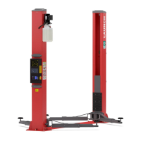
E
D
C
B
2#
A
1#
3107mm(122.32in)
131mm(5.16in)
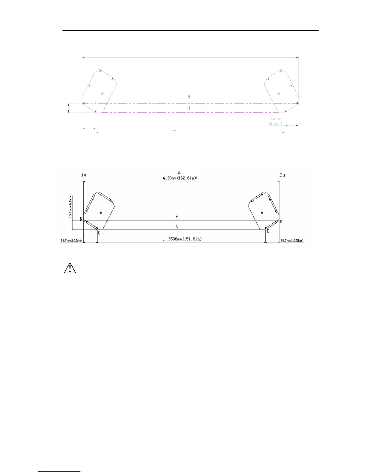
228mm
(8.98in)
3563mm(140.28in)
F
Fig 6a
Fig 6b
Note:
z All the dimensions are based on the external
border of the base plate.
z Ensure the overall error is controlled within 6mm.
In this way, the difficulties in the final assembly
can be eliminated.
z The marking and layout is very important. If it is
inaccurate, there will be problems during the final
assembly and operation.
5.2.3 Install the powerside column
First install extension column with column, then use lifting
equipment to place power side column to the location as
Fig.7 shows. Align the base plate of column with the chalk
line layout. Guided by holes on the base plate of the
column, use 5 concrete anchor bolts to fix it onto the
ground. Drill and install anchor Bolt s at one time, during
the drilling process, ensure no movement of the
column.(Fig.7)