Launch TLT245AT / TLT250AT(C) Two-post lift’s Installation manual
9
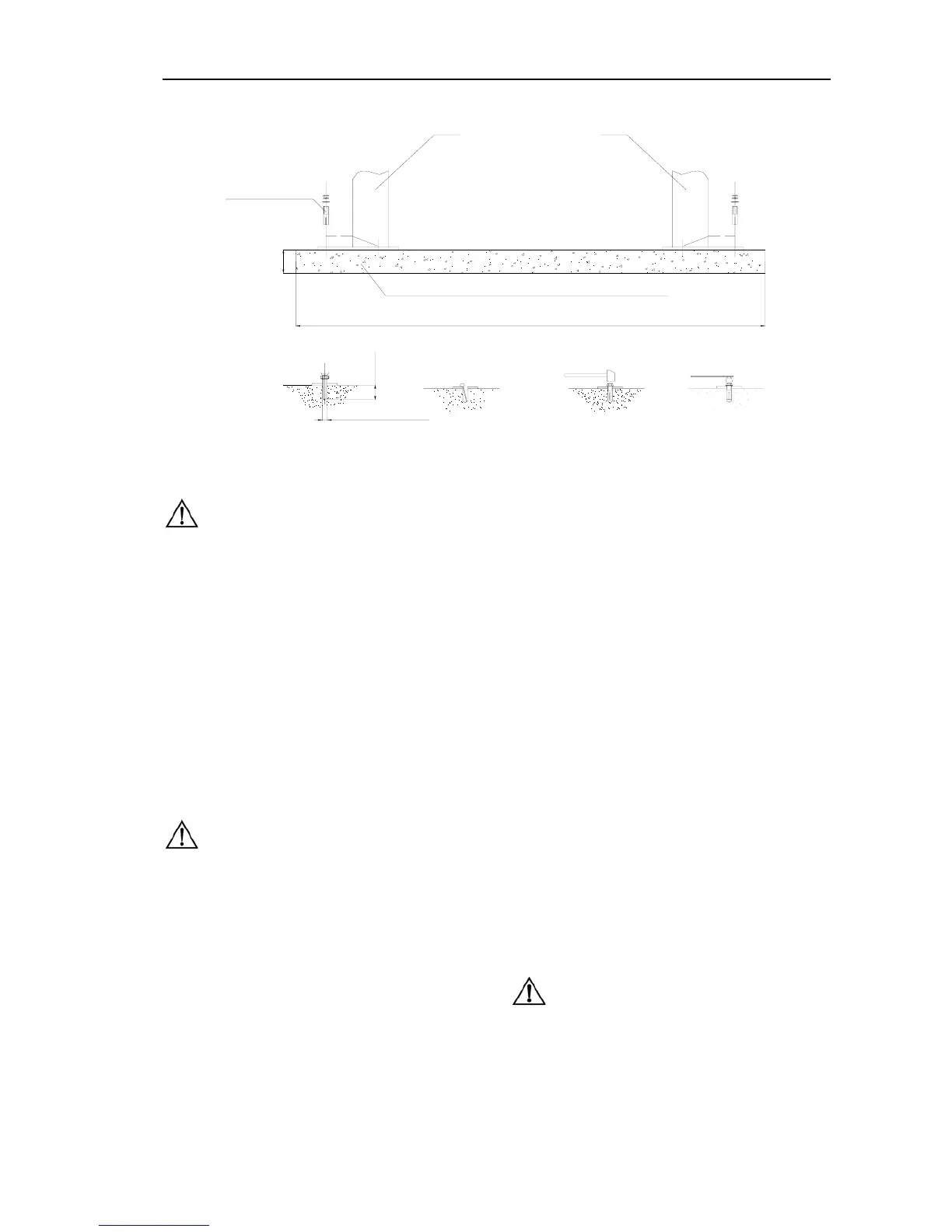
M19× 140
250mm
(9.8in)
anchor bolts
Expand
Dilled hole
Clean
Fasten
Foundation concrete intensity above3000PSI(2.1Kg/mm )
Column
150mm
(5.9in)
2
Column
2
φ 19mm(φ 0.75in)
4000mm(157.5in)
wide:1800mm(70.9in)
Fig.7
Notes:
♦
Use sharp
Φ
19mm concrete drill-bit to drill the
holes so as not to drill the hole too large,. Use
proper pneumatic tool to remove the dust from
the hole. The depth of the hole is the same as that
of the anchor Bolt . Insert the anchor Bolt and
make the washers lean against the base of the
column.
♦ When fastening the anchor bolt, only use the
(torque) wrench, and don’t use impact tool for
fastening.
Insert proper steel shim under the base seat of
column to plumb the column
Note: The thickness of shims shouldn’t exceed
5mm.
To get the correct and safety installation, please follow
the following installation steps.
z Wear the safety goggles
z Use hard alloy drill-bit.
z Don’t use the drill-bit with wearing exceeding the
tolerance.
z The drill and concrete surface should be kept
perpendicular.
z Let the drill work itself. Don’t apply the extra force,
and don’t ream the hole or allow the drill to wobble.
z The drilling depth of hole is based on the length of
anchor Bolt .The distance from the Bolt head to the
concrete floor should be more than twice of the Bolt
diameter.
z Remove the dust from the hole.
z Gently tap the Bolt into the hole till the washer rests
against the base plate of column.
z Fasten Bolt s
5.2.4 Install the top beam
Position the offside column at the designated chalk location.
Lift the top beam to its high position, and use bracket and
fasteners to fix it with the columns (as shown in Fig. 8).
When installing the top beam, ensure the above micro
switch support bracket adjacent to the power side column.
In Fig 8:The symmetric top pulleys are to be installed at
position 1、1″,asymmetric top pulleys are to be installed at
position1、1”、2、2”
Note: Since the offside column is not fixed to
the ground, you must operate carefully to avoid the
falling of the column.
10 sets